If you want to run DC current through your transformer you won't need the active load, but you will need a transformer designed for the current.
All good fortune,
Chris
Chris,
sorry I do not understand, but where there is DC through transformer? Current goes through transformer and through U1tube which is not opened constantly, modulated by grid, is my understanding incorrect?
Yes, in LTSpice I see that some DC current flows through transformer.
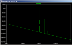
Also I looked to FFT and it has too much even harmonics.
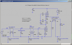
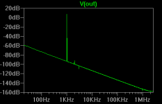
I've get back to transformer connected to cathode branch (ground).
It shows following FFT. Is it good or still has to much even harmonics?
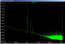
though I see second and fourth harmonic started appear in cable (third pictire).
What would you suggest to improve this?
Also I looked to FFT and it has too much even harmonics.
I've get back to transformer connected to cathode branch (ground).
It shows following FFT. Is it good or still has to much even harmonics?
though I see second and fourth harmonic started appear in cable (third pictire).
What would you suggest to improve this?
Attachments
Last edited:
By playing with values I've managed to make Total Harmonic Distortion: 0.001096%.
(I tried with cap instead of tr, but it gives 0.1% THD)
I have following questions:
1. How to further improve the amp so it does not distort?
2. Where to get real data for input and output transformers - inductance of coils, capacitances etc? Can it be deducted from impedances and resistances?
3. Would it make sense to change LED to tube diode like 0D3?
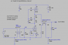
This is my first tube preamp project. Dear Experts please take a look and comment.
Thanks!
(I tried with cap instead of tr, but it gives 0.1% THD)
I have following questions:
1. How to further improve the amp so it does not distort?
2. Where to get real data for input and output transformers - inductance of coils, capacitances etc? Can it be deducted from impedances and resistances?
3. Would it make sense to change LED to tube diode like 0D3?
This is my first tube preamp project. Dear Experts please take a look and comment.
Thanks!
Attachments
even harmonics is a desirable effect on a tube mic pres. otherwise, you would use a SS based mic pre like a Jenson 990 , API 312 or a Neve 1073.
I wouldn't even do an led in the cathode. All ccs does bad things for sonics, granted it makes it operate nicer, but at a cost. Just a nice quality resistor would do.
build it. simulators can only simulate the circuit to a point.
I wouldn't even do an led in the cathode. All ccs does bad things for sonics, granted it makes it operate nicer, but at a cost. Just a nice quality resistor would do.
build it. simulators can only simulate the circuit to a point.
even harmonics is a desirable effect on a tube mic pres. otherwise, you would use a SS based mic pre like a Jenson 990 , API 312 or a Neve 1073.
I wouldn't even do an led in the cathode. All ccs does bad things for sonics, granted it makes it operate nicer, but at a cost. Just a nice quality resistor would do.
build it. simulators can only simulate the circuit to a point.
Thanks, Daves!
My idea is to built a preamp as soon as I've built my mic.🙂
SS schematics are complex, tube schematics are more DIY-able.
Also glowing tubes look cool.🙂
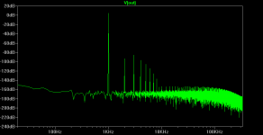
With tube 0B2 and R9 1K I've got Total Harmonic Distortion: 0.000496%.
THD grows with changing R9 from 1K to either lower or higher (why?😕).
I'll may be put a switchable resistors somewhere there to produce some colorations. Though my idea was to make a clean preamp to make studio recordings, then effects can be added later. Ribbon mics are usually very neutral, so I think a neutral preamp should match the idea.
I'll build it. Just do not want to build a badly designed one.
Also after I build it I do not know how to measure it. I even do not have oscilloscope. I have quite good sound card (EMU0404) that I hope can be possible to use to produce input signal and take output one to analyze with some programs.
zero gas tubes. too high resistor would drop too much voltage and choke it and too little resistance would generate more white noise (and have a tendency to HF oscillate). simulation software is assuming a certain impedance characteristic thay may or may not be true in real world applications..
gas tubes are noisy and very few designs are out there for audio because they have to be hand pick for lower noise.
gas tubes are noisy and very few designs are out there for audio because they have to be hand pick for lower noise.
Done mean to go back to far in the conversation, but how could a capacitor produce so much more THD in comparison to a transformer? I would have always figured an iron-cores magnetic field would be more sluggish than a capacitors surface area.
And if it came to the point of not being satisfied with just a resistor, what if you did a cathode bypass with some nice capacitor? Wouldn't it bring up the gain per-se? What about quality / distortion?
And if it came to the point of not being satisfied with just a resistor, what if you did a cathode bypass with some nice capacitor? Wouldn't it bring up the gain per-se? What about quality / distortion?
how about a battery. a 1.2-1.5V battery instead of led. negative to ground and 1k resistor. or even 1K resistor to ground. batter in input transformer, battery positive to ground grounding side of transformer is connected to negative side of the battery.
also run the output balanced.
+ tip - ring
and don't ground the transformer output, or even the sleeve on the trs.
if you need to attenuate, do it after the pre. as you don't want to record the noise floor that would be present regardless of volume control setting.
+ tip - ring
and don't ground the transformer output, or even the sleeve on the trs.
if you need to attenuate, do it after the pre. as you don't want to record the noise floor that would be present regardless of volume control setting.
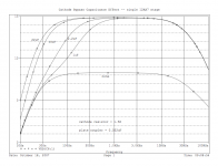
Just for food for thoughts, check out this graph showing bypassed vs unbypassed with a capacitor on a 12ax7. Thoughts? How does this compare with a battery at the cathode? Distortion?
Also, how come you wouldn't want to ground the common after the transformer? Ive seen some with this suggestion and some without.
Also, how come you wouldn't want to ground the common after the transformer? Ive seen some with this suggestion and some without.
Attachments
Daves, thanks,
I've removed 0B2 and slightly increased cathode resistor R9 to 1k2.
Looks good.
Also I've changed tube lib from old Koren to Koren Improved.
That shows a little bit more THD, but I think it is more fair. The old one was too optimistic.
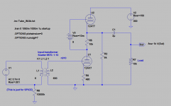
Now I am working on changing biasing of U2 tube to a battery.
This change promises no capacitors at all (unlesss the battery itself has some capacitance) and reducing number of resistors (less noise)...
I've removed 0B2 and slightly increased cathode resistor R9 to 1k2.
Looks good.
Also I've changed tube lib from old Koren to Koren Improved.
That shows a little bit more THD, but I think it is more fair. The old one was too optimistic.
Now I am working on changing biasing of U2 tube to a battery.
This change promises no capacitors at all (unlesss the battery itself has some capacitance) and reducing number of resistors (less noise)...
Where can I obtain the "new Koren" model? I want to make sure Im on the same page with these tests. I just ran a resistor set up vs a resistor diode set up. It looks like just a resistor appears to produce more distortion? I didnt think by this much...
Also check out no cathode anything. Dangerous?
Also check out no cathode anything. Dangerous?
Attachments
Last edited:
Thankyou mm7! This is great, thanks for sharing.
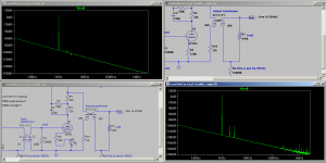
So as I try to play around with the FFT, I want to make sure I am understanding what I am looking at. From what I am familiar with, I know of the noise floor being horizontal. But in these simulations, the floor appears to descend through the decades. Is this right? What is going on here...
So as I try to play around with the FFT, I want to make sure I am understanding what I am looking at. From what I am familiar with, I know of the noise floor being horizontal. But in these simulations, the floor appears to descend through the decades. Is this right? What is going on here...
Attachments
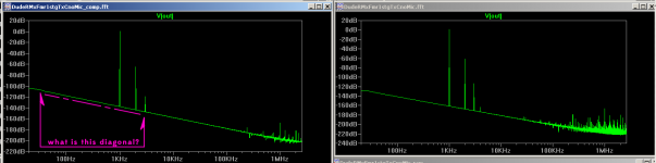
Ok, never-mind, I figured out what that slope was. The time start just needs to be pushed forward a bit. The circuit hasn't reached quiescence yet.
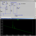
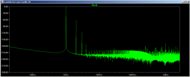
This is what I am more familiar with looking at...
This is what I am more familiar with looking at...
Attachments
Last edited:
that is right. The more inductance or/and capacitance of elements the more time it requires to stabilize. I usually run transient from 0 to 1-2 sec to see when it becomes horizontal, then set "start data" from that.
Couple of days ago I tried to find inductances of transformers, asked Marik to open inductances of his Samar transformers, but got no response.🙁
Now found an interesting article ... reading ... here
Audio Transformer Inductance
Couple of days ago I tried to find inductances of transformers, asked Marik to open inductances of his Samar transformers, but got no response.🙁
Now found an interesting article ... reading ... here
Audio Transformer Inductance
Interesting, perhaps this data/pdf may shed more accurate light on comparing methods.
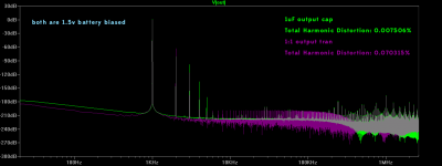
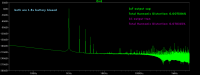
Check this out when I compared the transformer (with a coupling coefficient of 1) to a 1uF capacitor. Although the distortion is lower overall with the capacitor, its 3rd, 4th and 5th (and a bit of 6th) are more prominent.
Both of these are with battery biasing. (1.5v)
Any Explanation on why this is so?
Attachments
With 1mkF cap I get around .05% THD
Harmonic Frequency Fourier Normalized Phase Normalized
Number [Hz] Component Component [degree] Phase [deg]
1 1.000e+03 2.701e+00 1.000e+00 179.62° 0.00°
2 2.000e+03 1.331e-03 4.928e-04 88.44° -91.18°
3 3.000e+03 1.965e-06 7.276e-07 175.88° -3.74°
4 4.000e+03 4.898e-06 1.814e-06 1.28° -178.34°
5 5.000e+03 3.910e-06 1.448e-06 0.01° -179.61°
6 6.000e+03 3.256e-06 1.206e-06 0.01° -179.61°
7 7.000e+03 2.790e-06 1.033e-06 0.01° -179.61°
8 8.000e+03 2.440e-06 9.035e-07 0.00° -179.61°
9 9.000e+03 2.168e-06 8.028e-07 0.01° -179.61°
Total Harmonic Distortion: 0.049280%
could you show your THD from log (press ^L) ?
And Out voltage jumps to 100V then gradually going down getting horizontal on 4sec. This jump to 100v concerns me. Is it safe for humans and amps? Or it is artefact of LTSpice?
Question also is a battery really better for sound than a resistor?
Batteries have some (low) resistance and capacitance, and these are changing with temperature... Is it good to use them in sound signal circuits?
Last edited:
1. Due to difficulties to find an output 1:1 TF with high inductances that does not drop low freq, I've removed the output TF, and added Cap 2mkF.
Resistances adjusted to make THD 0.0035%. (though 3-rd and higher are slightly higher than 2-nd, I do not think it can be recognized at -84dB)
2. RC network that biases U2 grid is changed to battery 9V.
I read about batteries, they are complex beasts, have resistance, capacitance and impedance, and these are changing with temperature etc. hopefully these values are low
and battery conducts AC signal like a wire. If not, would it be better to change that back to RC network?
What batteries sound best? (Lithium, alcaline, NiMH..?)
Hopefully sound will not be worse from these changes.
People please comment!
Another question, what is better for sound quality:
a) step-up transformer 1:10
b) one more mu-follower stage
c) other?
Attachments
Both of these are with battery biasing. (1.5v)
Battery biasing on U1 cathode has some current (about 1mA), will it drain the battery fast?
- Status
- Not open for further replies.
- Home
- Amplifiers
- Tubes / Valves
- Ribbon Microphone Preamp