Hi Ruffrecords,
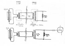
thankyou for the walkthrough! This is starting to shed some proper light on my confusion. I have attached some diagrams of me laying it out to make sense of it. One question I have rolling around in my head was : Grid leak resistors. Does the 150k act as a load and a grid leak at the same time?
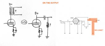
Also... What about the output stage of the preamp. That one diagram earlier had no output transformer... and no load resistor? What good would that drive?
For me, im interested in writing to my macbook which apparently presents a mic input impedance of 20kohms. What does this mean for the coupling part of this? Because of the high load... I could get away with a capacitor set up? or am I rather far off base here.
thankyou for the walkthrough! This is starting to shed some proper light on my confusion. I have attached some diagrams of me laying it out to make sense of it. One question I have rolling around in my head was : Grid leak resistors. Does the 150k act as a load and a grid leak at the same time?
Also... What about the output stage of the preamp. That one diagram earlier had no output transformer... and no load resistor? What good would that drive?
For me, im interested in writing to my macbook which apparently presents a mic input impedance of 20kohms. What does this mean for the coupling part of this? Because of the high load... I could get away with a capacitor set up? or am I rather far off base here.
Attachments
Hi Ruffrecords,
thankyou for the walkthrough! This is starting to shed some proper light on my confusion. I have attached some diagrams of me laying it out to make sense of it. One question I have rolling around in my head was : Grid leak resistors. Does the 150k act as a load and a grid leak at the same time?
Also... What about the output stage of the preamp. That one diagram earlier had no output transformer... and no load resistor? What good would that drive?
For me, im interested in writing to my macbook which apparently presents a mic input impedance of 20kohms. What does this mean for the coupling part of this? Because of the high load... I could get away with a capacitor set up? or am I rather far off base here.
Your diagram indicates you have a good grasp of what is going on in the transformers.
The input impedance of a tube is essentially infinite but for biasing purposes the grid does need to be referenced to ground. As there is normally no grid current you can use very high values of resistance but the actual value does not matter and is usually chosen to set the desired input impedance. So, in this case the 150K does both jobs.
Depending on the sensitivity of your mac book mic input and the loudness of your acoustic source, you might be able to simply connect the output of the 1:37 transformer directly to it without any intervening amplification.
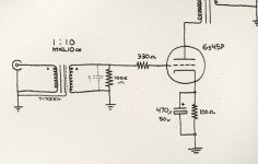
If you do need the extra gain then either of your proposed schemes will work. The 6AU6 wired as a triode was one of the very first tubes I tried as a mic pre. I used a 390 ohm cathode resistor and a 39K anode resistor which produced a gain of around 30dB. I would try the RC coupled scheme to start with. The resistor from the output capacitor to ground is there mainly to provide a dc charge path for the capacitor so its value is not critical - anything over 100K should be fine.. The output impedance is defined by the tube's plate resistance in parallel with the 39K plate resistor. I would guess this would be around 10K. This will drive a 20K load but it clearly does not meet the 10:1 impedance rule for no loss. This implies the transformer output might be a better option. One of the Edcor 15K:600 output transformers could work well here.
Cheers
Ian
Hi Ruffrecords,
Thankyou so much for these tips! Im slowly getting a much clearer understanding of whats going on!
Its actually perhaps a pleasant surprise that I don't need too much effort to get from mic to laptop. But I am still curious in educating myself on how to properly assess and design a amplifier stage by stage (understanding impedance etc). I have just been slowly taking my time in absorbing this information.
I just have one question while I think about these things: What are the cons of a RC coupled method? It just looks so damn simple compared to the transformer alternative. cost, size, and potential room for distortion. I also feel that transformers for coupling act as giant magnetic pickups from nearby EMI etc. Or is the big pro for people the impedance control?
Here is a mic preamp I want to build myself that I think you should consider.
Aikido Mono Solo
It has quite a bit of gain, should be very low noise, has a PCB available and is a proven design in the hifi realm as a preamp.
Aikido Mono Solo
It has quite a bit of gain, should be very low noise, has a PCB available and is a proven design in the hifi realm as a preamp.
Hi Ruffrecords,
I just have one question while I think about these things: What are the cons of a RC coupled method? It just looks so damn simple compared to the transformer alternative. cost, size, and potential room for distortion. I also feel that transformers for coupling act as giant magnetic pickups from nearby EMI etc. Or is the big pro for people the impedance control?
It's no surprise that its a little of them all. The main one is impedance and drive capability. As I mentioned, the output impedance of the 6AU6 triode stage will probably be in the region of 10K. This is too high to drive normal pro inputs which an input impedance of around 10K. Using the old 10:1 rule you really want the output impedance of the 6AU6 stage to 'look like' 1K or less. This is the main drawback of the RC method and where a transformer comes in. We need to transform 10K into about 1K so a turns ratio equal to the square root of 10 will be about right. This will be a step down transformer and the output will be 10dB lower. So our overall mic pre gain becomes 20dB from the mic transformer plus 30dB from the 6AU6 minus 10dB from the transformer which equals 40dB. No too bad but a little on the low side.
Modern transformers produce very little distortion at normal signal levels and are not really prone to magnetic pick up unless you do something silly like stick a mains transformer right next to them.
Here is a mic preamp I want to build myself that I think you should consider.
Aikido Mono Solo
It has quite a bit of gain, should be very low noise, has a PCB available and is a proven design in the hifi realm as a preamp.
I have never been a fan of the Aikido. It's only novel property is its ability to reject HT hum and that would only be necessary if you had a really poor HT power supply design. Since a low current HT supply (for a mic pre) with virtually no noise is pretty easy to obtain there seems little point in using an Aikido. You would be just as well of coming straight out of the SRPP and save yourself a tube.
Cheers
Ian
The Edcor Pri DCR is 0.4 Ohm, so with ratio of 1:37 you get 0.4x37x37+87=634.6 Ohm (!!!) of pure noise, while typically the DCR (or impedance) of the ribbon in RE154 kit is around 0.15 Ohm. IOW, the noise of the transformer will be dominating. On top the 87 Ohm Sec copper resistance also works as a voltage divider (unless you run it unloaded), so you are losing some more signal there.
Typically, for a good noise performance you need the transformer Pri DCR AT LEAST a decade below that of a ribbon, esp. when you are trying to use it with tubes and need to squeeze every last bit of dB.
While a second 1:10 transformer probably is a necessity in what you are trying to do, on the other hand you are getting transformer losses twice. Single 1:100--1:200 ratio transformer will be much better idea, but those are not cheap.
You might want to try a FET->tube cascode, which will considerably cut the noise.
Generally speaking, I don't see a good enough reason to use tubes with ribbon mics.
Best, Mark Fouxman
Samar Audio & Microphone Design, LLC
www.samaraudiodesign.com
Last edited:
Check out this Lundahl ribbon mic transformer. Primary resistance 0.05 ohms:
http://www.lundahl.se/pdf/2912.pdf
Cheers
http://www.lundahl.se/pdf/2912.pdf
Cheers
Hi guys, these are all excellent points that are brought up. Again, trying to take it all in.
Although in my peripheral, I would like to design a preamp. More specifically, a 6s45p. I havent drawn up the values yet (and all the transformers that would come attatched to it) but I was curious how this special tube would perform at small signal. I only hear great reviews about it.
And then for this noise deal, how exactly does resistance equate to dB of noise? the Lundahl you show here appears to have under half the quantity of ohms (264ohms) compared to the Edcor... which I purchased. I hear that people really dig the Edcor but what precisely am I combating here.
You are combating thermal noise. In a 20KHz bandwidth at room temperature the noise voltage in a resistor R is just the square root of R/3096 microvolts. So 634.6 ohms of resistance produces about 0.45 microvolts of noise which is about -125dBu. On a quiet source, a ribbon mic might need 70dB of gain so this noise will be 70dB higher at about -55dBu.
For the Lundahl transformer the resistance is about 127 ohms which gives a noise voltage of 0.197 microvolts or about -132dBu i.e it is 7dB quieter and after 70dB of gain it is -62dBu.
Note, a good low noise preamp will have an equivalent input noise of around -130dBu at 70dB gain. With the Edcor transformer its noise is the dominant one. WIth the Lundahl, it and the preamp are nearly equal contributors.
Cheers
Ian
Blast! I only find out about the differences now that I put in an order to the Edcor. But no worries, I don't consider this to be my last microphone.
The R/3067 microvolts at 20kHz room temp gets me the quantity of noise in microvolts... but how do I compare/view that to the actual non noise signal (formula?)? I want to compare at least by percentage (if that is an appropriate way of assessing).
Is this the Nyquist Noise coefficient? I definitely want to apply this rule to alot of things im looking at, but have to make sure I atleast know what it is called.
Blast! I only find out about the differences now that I put in an order to the Edcor. But no worries, I don't consider this to be my last microphone.
The R/3067 microvolts at 20kHz room temp gets me the quantity of noise in microvolts... but how do I compare/view that to the actual non noise signal (formula?)? I want to compare at least by percentage (if that is an appropriate way of assessing).
Is this the Nyquist Noise coefficient? I definitely want to apply this rule to a lot of things im looking at, but have to make sure I at least know what it is called.
This is commonly known as Johnson noise. Nyquist did a bunch of other good stuff.
If you work out the microvolts, take the log and multiply by 20 and then subtract 120 from the answer you get the noise level in dB relative to 1 volt.
The level of the signal depends on the sensitivity of your mic and the sound level reaching the ribbon. Ribbon mic sensitivity is specified in mV per Pascal (mV/Pa) of applied pressure and 1 Pascal is close to 94dB SPL. A typical low level output ribbon would produce 1mV per Pascal; the Royer ribbons have a sensitivity of around 2mV/Pa.
A mic producing 2mV output signal needs only 54dB of gain to raise the signal to 1V rms. However, if your sound source is a lot quieter the signal will be a lot lower. A human voice producing normal level speech at 1 metre from a mic usually produces a sound level of about 65dB SPL or about 20dB below the 94dB SPL reference level. The output signal will be 20dB less and so you will need 20dB more gain i.e. 74dB and so your noise level will be around 20dB higher too.
Hope that helps.
Cheers
Ian
Hi! It is very helpful to read this thread! So much info!
I also looking to build a tube mic pre.
I already have built my ribbon mic, it sounds good but sensitivity is not the best because of thick foil 5 or 7 micron. I'm going to re-ribbon it with thinner foil soon.
I also after to build mic pre. Currently I am going to repeat RCA OP-6 because of its famous gain 80+dB. It has 3 penthodes, RC coupled, and seems to me is quite DIY-able.
I target to neutral sound, not a "vintage", flat FR and minimum noise and distortions.
I also reading articles that I can find in web.
Looking for ribbon mic pre I found that it should be very similar to LOMC (low output moving coil) phono pres. Just should not have RIAA EQ.
Audiophile people uses DHT and some schematics use transformer coupling. DHT-s give good linearity and low harmonic distortions and transformers couplings also do not distort sound comparing with caps.
This article The Sound of the Machine I found very interesting and started looking towards this DHT/TC designs.
Unfortunately DHTs are not very high mu devices and it it looks like it is going to be 3-4 stages of them to produce 80dB gain. But it should be very pure and clean gain. And 4-5 trannies going to hit budget.
Could you comment on this?
Don't take that article too seriously. It makes some good points, but the author appears to have decided what he believes and then looked for evidence for it. Contrary evidence is brushed away.
For example, he says cathode degeneration is bad because it increases upper harmonics yet his figures show that mostly it does not. He arrives at the wrong conclusion because he has not thought through the issue of anode impedance versus load impedance. Cathode degeneration adds a linear component to anode impedance (assuming constant mu) so does not make things worse at the anode. On the other hand, it improves things at the grid by providing series feedback.
For example, he says cathode degeneration is bad because it increases upper harmonics yet his figures show that mostly it does not. He arrives at the wrong conclusion because he has not thought through the issue of anode impedance versus load impedance. Cathode degeneration adds a linear component to anode impedance (assuming constant mu) so does not make things worse at the anode. On the other hand, it improves things at the grid by providing series feedback.
One more critical issue- the loading of the secondary of the input transformer. If you just load it with the large value grid leak (which will be in parallel with the tube's Miller capacitance), it's likely to ring. Especially transformers with high step up ratios. Typically this is handled by a series RC network in parallel with the input transformer's secondary. The values of the RC usually have to be determined experimentally, but when you do so, be sure to drive the primary with the same source resistance as the mike+step-up transformer.
FWIW, I second Ian's recommendation of the LL2912 for the ribbon step-up transformer- that's what I used in my mikes and it worked superbly well.
FWIW, I second Ian's recommendation of the LL2912 for the ribbon step-up transformer- that's what I used in my mikes and it worked superbly well.
I agree with DF96. The real flaw in this article is that it only compares two topologies. The SRPP is well known to produce relatively high levels of distortion so it is not surprising that it is worse than the transformer coupled example. This does not mean that transformer coupled option is better than any other. For performance details of a different topology check out these articles:
http://www.ianbell.ukfsn.org/data/mufollowerdistortion.pdf
http://www.ianbell.ukfsn.org/data/6CG7mufollowerdistortion.pdf
heers
Ian
http://www.ianbell.ukfsn.org/data/mufollowerdistortion.pdf
http://www.ianbell.ukfsn.org/data/6CG7mufollowerdistortion.pdf
heers
Ian
One more critical issue- the loading of the secondary of the input transformer. If you just load it with the large value grid leak (which will be in parallel with the tube's Miller capacitance), it's likely to ring. Especially transformers with high step up ratios. Typically this is handled by a series RC network in parallel with the input transformer's secondary.
Many currently available 1:10 step up mic transformers (Sowter, Jensen, Cinemag) recommend a plain 150K resistor loading.
Cheers
Ian
Yes, but you don't get that in most designs because of the shunt capacitance of the first stage. The source impedance from the mike also changes the frequency response, so a blanket "just load it with 150k" is somewhat disingenuous. A few minutes with a square wave generator and a scope (as well as a few resistors and capacitors!) will pay great dividends.
dang, no joke, this is an absolutely useful conversation.
So what is this about ringing by loading? I feel like I have seen this before with CLC circuits. How does a RC on the secondary help ringing from happening? wont the capacitor suck up / degrade the signal in some way? And how does one pick the right value of capacitor for this occasion.
So what is this about ringing by loading? I feel like I have seen this before with CLC circuits. How does a RC on the secondary help ringing from happening? wont the capacitor suck up / degrade the signal in some way? And how does one pick the right value of capacitor for this occasion.
Attachments
Well, I see, transformer coupling is not a panacea.
So, what an ideal schematic that produces best(most neutral) sound and gives 80dB of gain would you recommend?
second question. Can we model schematics in SPICE and see gain, noise, THD etc..? instead of building real thing?
So, what an ideal schematic that produces best(most neutral) sound and gives 80dB of gain would you recommend?
second question. Can we model schematics in SPICE and see gain, noise, THD etc..? instead of building real thing?
- Status
- Not open for further replies.
- Home
- Amplifiers
- Tubes / Valves
- Ribbon Microphone Preamp