Peter or friends 🙂
Just received the kit from Peter and after plenty of reading, I feel ready to start... but one newbie question...
The LED from the rectifier.. I have a blue LED (5mm, 8,000mcd min, 3.3V, 50mA,) to go with a 25x25 transformer... On line calculators give me a 2w (then values from 480 upwards) but these figures seem low compared to Peters and the resistors seem huge in physical size...!
Is this right? Sorry for the newbie question.....🙂
Mine LED is 4V and 25mA and I still use 62K resistor for desired brightness. Whatever the calculator says, I would still start with 10K resistor and adjust from there.
Thanks Peter, can I just check what the supply voltage should be (is it 25v as I'm using a 25x25 transformer?) .... and is there any benefit in using the rectifier for the power or wrapping wire around the transformer to produce the voltage?
Thanks again....
Thanks again....
By stereo version I mean the use of a single transformer powering both channels. You could still use two separate rectifiers boards, but depending on wiring it may produce hum in some systems, so I always stick with a single rectifier board when using one transformer.
For demonstration purpose, I will install all the boards inside 3 x 1.5" U-channel, 1.25" aluminum extrusion. For normal listening, this is enough to dissipate heat from the chips, and when things get hot, you can always attach it to larger aluminum panel.
I will show a version with a potentiometer, and without, so stay tuned.
Please appologize if this question has been asked somewhere else in this thread.
But the potmeter You have a picture of there, is it one with the good oldfashioned loudnesstap on it?
If so, I am VERY interrested in where to buy theese.
I am repairing a lot of vintage stereo and pots with loudness-tap is very much asked for.
Peter, I Am putting together the kit I bought at the moment and was looking for a little feedback. I am planning to run a minidsp to actively cross over my speakers. I bought two kits to supply four channels, 2 tweeters and two woofers. To power this what would be the best solution? Do I run one toroid to power all of the channels or a toroid per kit? Is the anything special I need to consider for the wiring?
Regards,
Snibo
Regards,
Snibo
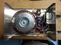
If amp and PS are in separate enclosures, I would suggest to place rectifiers with the transformer, that way you will have only DC in the amp. This may not be really critical, as I've built amps with rectifiers right beside the chip (see below) and they performed well, but placing the diodes in a PS enclosure is a common practice.
There are 4 wires in the umbilical: V+, V- and two grounds separate for each rail. While the example integrated amp had separate power wires for each channel (that's why you see 6) the Patek has power wires run from one channel to another channel (board).
Hello! Newbie here, first post... I rigged up a star ground between the two OG OUT points on the main boards and connected the V+ to V+ and V- to V- points just as Peter does for the umbilical power on the Patek from the post above. Now after nearly completing my build I realized I only used one wire in my umbilical for ground. What if any downside is there to not separating the grounds for each rail? I used #18 guage wire for V+, V- and the ground.
Thanks in advance for any advice! -Glen
Down the drain...
Well, I had a great few hours last night with the AudioSector amp I just finished building. It sounded great, no hum and the audio was crystal clear. I was listening to it through a pair of cheap KLH speakers and was really looking forward to hearing it through something better once I ran it in for a while. Here's a link to some pictures...
http://www.diyaudio.com/forums/chip-amps/79303-chip-amp-photo-gallery-241.html#post3483228
That was all short lived however. I got home from work today excited to settle in for some listening pleasure with my newly built amp. This was the first time I had it plugged into main power without the variac. When I switched it on, there was a brief loud hum from the transformer and a sharp crackle emanated from the speakers. That was it. From then on the amp was distorted and the heat sinks were burning hot. I checked the rails and they were uneven. 24.1v on one side, 26v on the other.
So the question is, how can I avoid another blow up like this after I rebuild this thing? Would a slow start circuit work? No one slow start circuit design seems to stand out on this site, which one works the best for this amp?
Thanks! -Glen
So the question is, how can I avoid another blow up like this after I rebuild this thing? Would a slow start circuit work? No one slow start circuit design seems to stand out on this site, which one works the best for this amp?
If the LM3875 kit is built correctly, you shouldn't need a slow start circuit. If you "borrowed heavily from that design," what did you do different? Was it only the physical layout, or did you make any circuit changes from the kit specs?Hello! I just finished building one of the excellent Audiosector LM3875 kits by Peter Daniel. I was inspired by Peter's Patek design, so I borrowed heavily from that design for my amp.
If the LM3875 kit is built correctly, you shouldn't need a slow start circuit. If you "borrowed heavily from that design," what did you do different? Was it only the physical layout, or did you make any circuit changes from the kit specs?
I was referring to the physical layout with only one exception. I used one ground wire between PG on the rectifier board and the star ground point at the amps. I tied PG together on the rectifier board using 14ga solid core wire and soldered that single ground wire to the middle of that.
I turned the amp on and off many times and listed to it for hours before this happened. Looking my project over, I can't see anything I did wrong. It just seems like that huge toroidal transformer just surged when I turned it on that last time. It is a brand new transformer. Is it possible that the transformer is defective?
Any idea what could have been damaged? Should the caps and resistors be okay? My thought is to replace just the LM3875s and try again...
Beginners should never omit the "optional" stability and filtering components.
How about some detail. Which ones, and what would they have done to prevent this?
You can measure the transformer's output, to see if it is functioning correctly, and measure the output of the rectifier board.I turned the amp on and off many times and listed to it for hours before this happened. Looking my project over, I can't see anything I did wrong. It just seems like that huge toroidal transformer just surged when I turned it on that last time. It is a brand new transformer. Is it possible that the transformer is defective?
When you first assembled the amp, did you measure it's DC offset?
You can measure the transformer's output, to see if it is functioning correctly, and measure the output of the rectifier board.
When you first assembled the amp, did you measure it's DC offset?
Hi Lightman, thanks for your reply... I measured the transformer's output on both sides AC and DC before I hooked it up to the amplifier for the first time. The voltages were matched and stable. I did not check the DC offset when I powered the amp up for the first time. I went straight to the speakers and supplied an input signal using an old Microsoft Zune I had laying around. The amp sounded great and I was very pleased! What did you have in mind with the DC offset?
The problem happened the next day after I moved the mains plug from the variac to a power strip and switched on the power supply with the amp hooked up. I assume the amp was working properly until then as it was quiet, cool, and sounded clear and good.
AndrewT suggested I use filters, so I explored this site a little more and found Nuuk's excellent article edited by AndrewT here: Building a Gainclone chip amp power supply.. My plan now is to add that "safety earth connection" circuit to the PSU, fuse the DC side and add the 10uf caps that came with the kit. I have new LM3875TFs on order for the amp, so I'll replace those and try again.
Thanks! -Glen
My Gainclone is alive and well!
Thanks to all the help on this forum, my gainclone is fixed. Turns out the amp was actually fine, it was the speakers that blew. The power supply was also fine, but it is now in an enclosure with proper grounds and it is quiet when turned on and off - no audible hums from the toroidal or pops in the speakers. Speaking of which, with a different set of speakers the amp sounds good again.
These new speakers are 4 ohm and the amp is running a little warm. I am hoping the amp runs cooler when I go to the 8 ohm full range speakers I am building.
Thanks again for the guidance.
-Glen
Attachments
ebay?
hello Peter
thanks for the nice thread..😎
i'd like to build an amp prefer on your LM3875 Premium Kit , did You sell it on ebay? please inform me,
many Thank
hello Peter
thanks for the nice thread..😎
i'd like to build an amp prefer on your LM3875 Premium Kit , did You sell it on ebay? please inform me,
many Thank
Even though I can't find any good quality component in my town, i decide to make my first gainclone... and yes it is good indeed the gainclone... thanks for this thread..
Larger psu caps, where to fit?
I'm currently using the premium lm3876 kit on a plywood test board so I can try out different set up's before making an enclosure to suit. Currently I have the kit set us as standard (1500uf on amp, no PSU caps). I would like to try 3x 3300uf per rail, I have these soldered together so that only 2 legs need to fit through the PSU PCB. I don't know though if its OK to make it fit in the small pcb hole, or if there are alternative cap holes I can use. Any advice if its OK to use this capacitance and also how to fit greatly appreciated.
Cheers Andy
- Home
- More Vendors...
- Audio Sector
- Commercial Gainclone kit- building instructions