I don't like to think of the possibility the output shorted to +V or -V 🙁
Who does. Fuses are on PSU, if that is what you are refering to.
The FR4 material I use has a dielectric strength of 20kV/mm, and it is 3kV/mm for air. For an amp operating on perhaps +/-40V what's the risk? I understand there are specific requirements for un-isolated mains, but at lower voltages and behind galvanic isolation the clearances can be much tighter. I understand the specification for the intended voltage range is 0.6mm / 0.024", so at 1.27mm / 0.050" things should be fine.
Hi naf,
Your peeceebee 2sa/2sc version based on shaan almost 8 hours now and still singing🙂🙂 Thank you naf for sharing peeceebee layout.🙂
Regards,
Boyet
Your peeceebee 2sa/2sc version based on shaan almost 8 hours now and still singing🙂🙂 Thank you naf for sharing peeceebee layout.🙂
Regards,
Boyet
Hi naf,
Your peeceebee 2sa/2sc version based on shaan almost 8 hours now and still singing🙂🙂 Thank you naf for sharing peeceebee layout.🙂
Regards,
Boyet
Yeah nice to hear and you liked it...

Yeah nice to hear and you liked it...
Yes and i liked it.🙂 I used 2sa1381/2sc3503 for driver and 1k for bias. Its good to my taste.🙂🙂
naf i have pm to you.
Thanks
Boyet
Hi naf,
Your peeceebee 2sa/2sc version based on shaan almost 8 hours now and still singing🙂🙂 Thank you naf for sharing peeceebee layout.🙂
Regards,
Boyet
Hi Boyet!
Just for reference...
Could you post some measurements of your build?
DC offset
AC offset
PSU you are using
Are VAS transistors warming up?
I built ver 1.4 using different devices and is now working but it still needs more test.
Thanks!
BTW. Many thanks to Naf for sharing the lay-out 😎
The FR4 material I use has a dielectric strength of...
Not about that... Just in case the copper is not sealed, stupid things can happen, mostly during testing. Even if the chance is small, when expensive speaker is used, that chance must be eliminated.
Hi Boyet!
Just for reference...
Could you post some measurements of your build?
DC offset
AC offset
PSU you are using
Are VAS transistors warming up?
I built ver 1.4 using different devices and is now working but it still needs more test.
Thanks!
BTW. Many thanks to Naf for sharing the lay-out 😎
Hi Abiter,
Just for reference...
Could you post some measurements of your build?
DC offset - I got 0.0mV after 2 minutes warm up. I set 0.1DCV on the tester. see the tester in the picture.
Calibration - On the 15K Of negative side -V I parallel 78k. Or you can Use 100k trimmer for calibration of dc offset.
and also I parallel 15K in 1000uf. You can do it different value until you can achieve 0.0mV
AC offset - I dont know.
PSU you are using - +-35Vdc 4A. 2pcs. 4700uf/50v only for testing. never tried higher uf I dont have.
Are VAS transistors warming up? - Yes. I Put heatsink to driver.
Do you tried BC550C/560C for the input? Where did you buy?
Thanks,
Boyet
Attachments
![Photo0176[1].jpg](/community/data/attachments/328/328718-d0600dcf55cd96c9a1524b6b3b14ff58.jpg?hash=0GANz1XNls)
![Photo0183[1].jpg](/community/data/attachments/328/328727-9db96f04f27bf6ca1e8d4f7efc55c9ea.jpg?hash=nblvBPJ79s)
![Photo0174[1].jpg](/community/data/attachments/328/328733-4a3d3714599dee701249ed3f611f4744.jpg?hash=Sj03FFmd7n)
![Photo0169[1].jpg](/community/data/attachments/328/328739-cf6bc8c5c97c6ee7e89c330a6641b206.jpg?hash=z2vIxcl8bu)
![Photo0170[1].jpg](/community/data/attachments/328/328748-c24cebe8e81490c533c733eaccd95b99.jpg?hash=wkzr6OgUkM)
Do you tried BC550C/560C for the input? Where did you buy?
Thanks,
Boyet
Hi Boyet!,
0.0mv wow! that is perfect to the ideal dc offset of an amp.😎
Measuring AC-offset is the same procedure as dc-offset only that your meter is set to ac. Ideally should also be 0mv when no signal applied. Occurence of high AC-offset could mean oscillation problems (self-generated noise).
I was using the higher voltage BC556B/546B at the input differential. BC550C is available in Raon but the complementary pair BC560C is nowhere to find...😀
One of these days I will also try Nafs variant as I still have 2SC2240/SA970 in my stock.
Regards!
AC on the output when the input is shorted is noise.
It can be hum and/or white noise.
Try loading the input with different resistors. I keep dummy load RCA's for just this testing: 0r0, 100r, 1k, 10k, 100k in pairs. Use cheap plastic RCA plugs.
AC noise on the output is not output offset.
DC on the output is output offset.
It can be hum and/or white noise.
Try loading the input with different resistors. I keep dummy load RCA's for just this testing: 0r0, 100r, 1k, 10k, 100k in pairs. Use cheap plastic RCA plugs.
AC noise on the output is not output offset.
DC on the output is output offset.
Not about that... Just in case the copper is not sealed, stupid things can happen, mostly during testing. Even if the chance is small, when expensive speaker is used, that chance must be eliminated.
I get what is being said. I'm not too concerned about such things, others may feel differently. By the time the amp ever gets connected to my primary system it is already tested and in an enclosure. At that point the risk is essentially mitigated. My 2¢.
Argh, just stopped into the local print shop to pick up my film to find they created a negative instead of a positive. All my pre-sensitized boards and my developer are positive chemistry. No PeeCeeBee's will be etched this weekend 🙁
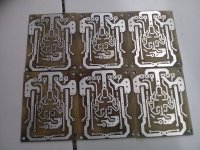
Finishing 3 pairs peeceebe of bc550/560 version
1 pairs for me, 2 pairs going to my friend.
Hi Naf, nice.. very neat your pcb 🙂
I bought parts for 2 channel of peeceebee except bc550/bc560 because no available. I have ordered bc's..2sa/2sc still singing🙂🙂🙂 naf may I request also the bc550/560 peeceebee version? Thank you.
Regards,
Boyet
Hi Shaan,
I have defective sr4300 marantz and I plan to use the power supply -50v +50v.
What value will be changed in the schematic of peeceebee? I do hope your reply my inquiry.🙂🙂 Thank you.
Regards,
Boyet
I have defective sr4300 marantz and I plan to use the power supply -50v +50v.
What value will be changed in the schematic of peeceebee? I do hope your reply my inquiry.🙂🙂 Thank you.
Regards,
Boyet
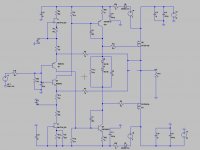
my project of VSSA
... with FET curant sources: better stability vs supply voltage, R4 and R5 to limit voltage (and heat) across fets, R9 to fine tune V offset (I will first put a variable resistor then replace with a fixed one)
different supply voltage for input and VAS (use of SMPS 800RE)
10x gain (I bought udj6 6 ways soundcard with 3 volts peak).
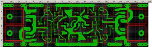
and since my project is active speakers the corresponding PCB for two channels on one board, common VAS supply, common VAS ground, separate ouput grounds.
PCB size 60mmx200mm
I'll be ordering PCB quite soon, GB possible ....
any comments?
cheers
Paul
... with FET curant sources: better stability vs supply voltage, R4 and R5 to limit voltage (and heat) across fets, R9 to fine tune V offset (I will first put a variable resistor then replace with a fixed one)
different supply voltage for input and VAS (use of SMPS 800RE)
10x gain (I bought udj6 6 ways soundcard with 3 volts peak).
and since my project is active speakers the corresponding PCB for two channels on one board, common VAS supply, common VAS ground, separate ouput grounds.
PCB size 60mmx200mm
I'll be ordering PCB quite soon, GB possible ....
any comments?
cheers
Paul
Attachments
Mr.Shaan goodnight, when you publish peeceebee VSSA .. because my friends and fellow DIYers wait layout and component layout by shaan version. there a change in layout and component layout?
I'll be ordering PCB quite soon, GB possible ....
any comments?
I have one pair each of Exicon ECX08N16-Z/ECX08P16-Z and like your version of VSSA, especially practicality since both channels are on one pcb. Could you provide one pcb for me? I shall contact you with PM for payment.
- Home
- Amplifiers
- Solid State
- PeeCeeBee