Oh no!
KSA992 in the current mirror! This needs corrected. These have abysmal Vcesat. It is so frustrating how long it took for me to learn about quasi-saturation in BJTs. This one thing may be holding the real DiyAB back.
Look at the datasheet. I'll make it terrifyingly obvious:
http://www.fairchildsemi.com/ds/KS/KSA992.pdf
Look at the Vce vs. Ic chart. You'll see that at .6V Vce, the collector has a V/I slope of 143. This is the definition of a collector impedance of 143R! To see the effect of this in simulation, put a 280R resistor across the CM collectors.
This is a mistake I made when designing my Kmultipliers. NEVER use high-voltage BJTs for Vce below 2V!
The simulator doesn't show this because quasi-saturation is not modeled.
I tested a number of transistors in the Kmultipliers and 2N5551/5401, 2N5089, KSC1845/A992, and so on always fell short. Ultimately the BC5x0 and BC3x7 series were the best. These have high collector impedance at very low voltages. The BC3x7 are the best, but are slower - but with low Re/Rb and great surge capability, perfect for a frontend C-multiplier filter.
I suggest BC560C for the current mirror. I've also measured these, and found they were generally within 300uV Vbe (OnSemi IIRC), so you'll have almost perfect current balance from the start.
If you want to try it, just replace Q5 and Q6 with BC560C. Schematic:
http://www.diyaudio.com/forums/imag...YAB-2V20/P-DIYAB-2V20-diyAB-amp-schematic.pdf
Last edited:
I built the mongrel amp (which this design came from) with the 2 output transisters NJW03, NJW0281 mounted on a conrad 300 heasink for each channel and a single 300va 45v transformer 60v rails. This ran fine while driving 6 ohm speakers, however blew the outputs when I cranked up the volume
Please note that I'm using two 4281 and two 4302 on one heat sink per channel.
Still at risk here?
-Chas
I'm no expert but can say from experience that it is risky. I built the mongrel amp (which this design came from) with the 2 output transisters NJW03, NJW0281 mounted on a conrad 300 heasink for each channel and a single 300va 45v transformer 60v rails. This ran fine while driving 6 ohm speakers, however blew the outputs when I cranked up the volume on a set of diy mini statements which go down to 4 ohm.
I agree. This amp seems a bit fiddly to get right.
Happy New Year everyone!
The Honey Badger prototype I used in the build guide has already survived two New Year's eve celebrations. ;D
The Honey Badger prototype I used in the build guide has already survived two New Year's eve celebrations. ;D
🙂
First of all , Jojo's construction PDF is VERY well done ... and the boards are so nice I am considering a purchase.
I test all types of used speakers and sources at the thrift shop I work at. And guess what I use ? .... the original AX/(badger)! I blew the rail fuses twice with
PA speakers(cheap/4R) , one time just the negative rail fuse blew and the amp sounded distorted but had no offset.
I started using this amp because the OEM test amps would not survive too long.
The badger is also much better at auditioning all these used speakers (they sell quick after the customer hears all that headroom 😀) I repair many Sherwood/KLH/Sony discrete receivers/amps and they are inferior (sound/durability).
As far as instability ,😀 !! With 10pf miller compensation .. maybe ? (I detected minor ringing with a single 22pf silver mica) ,but the amp still was rock solid.
The DIYaudio badger PCB has a better layout than my "hacked" (recycled)
prototypes , so it should be even more bulletproof.
Really good work.. guys !!
BTW , my account was not hacked .. my brain was 🙄 .
OS
Thanks man, and welcome back. 🙂
The one you remember having busted outputs immediately after building the amp has been figured out already. It was the builder's fault not the circuit, he forgot to mirror the pcb when he cloned it, hence, most of the transistor leads were installed the other way around...
I do believe this may be my amp you are talking about. It is true I built the boards as a mirror image but "untrue" that this was to blame for the amp blowing power transistors as the transisters were installed mirror image to suit the mirror imaged board.
Hello,
I am having issues of burned out power transistor.
If anyone do not have burned out issue yet, it may simply indicating that those three transistors are not fighting hard enough yet.
I also remember someone else has the similar issue immediately after building the amp.
Any thought ? Any input is appreciated.
With this board ostripper had many options for builders during the build. 2 different cascodes/current mirrors to choose,2 different vas compensation modes, a choice of the builder for their vas standby current, choice of R27 size and the choice of using an lead compensation capacitor as well(I do not recommend using an LC cap), as well as many transistor choices as well. All these will have an effect on how stable this amplifier will perform in the real world.
I can only recommend the choices I made to cure my amp issues (which weren't a result of a mirrored pcb). It gets quite warm here in summer as repeet would be able to attest to. 38deg c yesterday. I found that q10,q11,q12 heatsink got quite warm and needed a larger heatsink, or better yet tie those transistors to the main heatsink instead of using a separate smaller one.
The choices that were made for my amp were
1. Use the zener referenced cascode/current mirror.
2. For vas compensation I used option 1 the CMC compensation method.
3. Did "not" use a Lead compensation cap. This was tested and the resultant sound was horrible.
4. Changed R27 to 100r. And adjusted to 0.6v across it (6ma).
5. The larger heat sink for q10-12 as stated before.
Has been running like a dream with no blown transistors since.
Regards
Simon
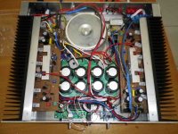
PS. The amps is different to the pic now and a bit neater. The remote volume control boards at the front are removed (chinese ebay type I dont recommend). Solid state relay at top left is removed as well. Now it just houses the soft start and power amplifiers.
Attachments
I do believe this may be my amp you are talking about. It is true I built the boards as a mirror image but "untrue" that this was to blame for the amp blowing power transistors as the transisters were installed mirror image to suit the mirror imaged board.
Hi niss_man,
I can hardly remember if it was yours but thanks for clarifying. I think I remember that the amp was powered up before it was discovered that it ain't a mirror image of the board, or was it?
Anyway, what caused them output transistors to blow up again?
It is no secret that I've been trying to blow up this amp ever since I built it.
I found that q10,q11,q12 heatsink got quite warm and needed a larger heatsink, or better yet tie those transistors to the main heatsink instead of using a separate smaller one
2 ways to fix this...
A. - Lower the [CCS adjust] , this will bias the VAS differently. 2.5ma in the CCS will equate to approximately 6.5ma in the VAS.
B. - Change R27 as nissman pointed out. Member MJL21193 often stated that 5-6 mA was the "sweet spot" for the 1381/3503 pair. This would allow for running the CCS at 3-4ma as recommended.
Member Keentoken also has a point
about the current mirrors.KSA992 in the current mirror! This needs corrected. These have abysmal Vcesat. It is so frustrating how long it took for me to learn about quasi-saturation in BJTs. This one thing may be holding the real DiyAB back.
Replacing Q 5/6 would be simple , only the pair would be back-back instead of face-face. This improved current balance would indeed reflect on the sonics .. even if only by a small amount. This is explained in Hugh Dean's AKSA threads.
It is no secret that I've been trying to blow up this amp ever since I built it.
Same here.. but I have almost 2 years on mine.
OS
🙂
First of all , Jojo's construction PDF is VERY well done ... and the boards are so nice I am considering a purchase.
Really good work.. guys !!
OS
Just PM me your address and we'll send you a couple of pairs!
Welcome back, we all need a break now and then..
Mark

if Q5-Q6 can be replaced by BC560 i guess that BC550C would be ok as well
what about Q9? Can we replace with BC560 or BC550?
thanks
what about Q9? Can we replace with BC560 or BC550?
thanks
If you have more than 40V rails BC560C couldn't be used for Q9. Q5/6 never see more than a volt barring lightning strikes or cometary impact so they don't need high Vcemax. Q9 doesn't have low Vce so KSA992 here is no problem. You want a very high-gain fast transistor in this position.
Does anyone here build DiyAB Honey Badger amp with out stability issues?
Was this said in humor ? Of ALL the amps I built ... this one actually was put together without a miller cap using a mje340 VAS. Just a warm Zobel 😀 .. . Of ALL my prototypes , .. this one is the most "forgiving" ,.. and the best documented (Self and Cordell). So if this was a "trolling" attempt , wrong place-wrong amp!! .
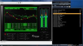
PS ... amp is nearly idiot proof and burn proof - me and Jojo have experienced
this. I even use this amp while I type this (below-awesome source). Nothing but the best for my fellow DIY'ers .. 🙂 .
OS
Attachments
barring lightning strikes or cometary impact
Well said , Keen .. 😎😎 . goes the same for the badger !!
OS
thank kean/os , gonna replace ksa992 with bc560c in Q5/Q6.
do i have to hfe match of this transisitor?.
thank you.
my build of this amp is rock stable! i follow all build guide by jojo and only change ksa1381 with 2sa1209.
do i have to hfe match of this transisitor?.
thank you.
my build of this amp is rock stable! i follow all build guide by jojo and only change ksa1381 with 2sa1209.
do i have to hfe match of this transistor?.
Not required , but the audiophile in you might WANT to .. 😀
PS - Q1 and 2 are also candidates for matching , this will result in less offset.
The ideal is at least a close DMM match of 1-2 and 5/6, but the amp will still be
better than most with even recycled parts.
OS
Last edited:
Not required , but the audiophile in you might WANT to .. 😀
OS
thank you OS , i'll hfe match of this transistor.
naf
of course i match q1/q2 and guess what offset i got?... my dmm read 0.00mv 🙂
i gain knowledge from your thread... from frugal to mongrel 🙂...
my deepest thank you
i gain knowledge from your thread... from frugal to mongrel 🙂...
my deepest thank you
By Tsip - if Q5-Q6 can be replaced by BC560 i guess that BC550C would be ok as well what about Q9? Can we replace with BC560 or BC550?
thanks
Q9 sees nearly the full rail voltage , might want to keep a high Vce device (2sa992) here.
OS
Hfe matching won't help. Vbe matching is what's important for a current mirror. Most BC5x0C I've measured are matched to 300uV. That's a just over a 1% mismatch. 1% at 3mA is 30uA. And this is without degeneration! Now lets consider temperature to make sure.
Q5 has about 1V Vce whereas Q6 has .66V. This corresponds to 3mW and 2mW respectively. The thermal resistance from junction to ambient of the average TO92 is 200, so this calculates to a temperature difference of .2C. The tempco of silicon is about 2.1mV/C, so we have a 420uV mismatch. So this leaves us with a 720uV total mismatch. This is 2.8%, corresponding to a mismatch of 84uA. If the cases are thermally coupled, differential thermal resistance is about 160 corresponding to a mismatch of 336uV.
And this is still without any degeneration.
Assuming an Hfe of 500 for the BC560C, mismatch caused by Hfe will be roughly 12uA. So improving matching by a factor of 8 with equal Vce and degeneration is the point of diminishing returns. BUT there is 220R degeneration in the original design. So lets factor this in. 720uV mismatch across 440R total degeneration means our Vbe-induced mismatch is reduced to 1.6uA - .005%! Despite mismatch and temperature variations, the biggest flaw with our current mirror is not a transistor mismatch. Of course, the degeneration tolerances will directly affect matching, so they are in fact the weakest link. Two 5% tolerance resistors have a potential mismatch of 10% - almost 4 times the max mismatch without any degeneration at all!
So, match R20/R21 first and only then worry about Vbe mismatching with the BC5x0C. You can check Vbe matching with your multimeter at the diode setting by placing the probes across the B-E junction and making sure they both match to 1mV (4%) or so. Let them sit a while and don't touch them with your fingers when you do this.
If you have matched R20/R21, you can verify transistor matching by probing across the emitters of Q5/6 with your DMM. It should be less than 1mV; short your DMM leads to make sure it can read DC below 1mV. Don't have a speaker connected while probing around in the amp. Even if you don't slip or drop a probe, touching the sensitive signal nodes may cause oscillation which could be dangerous for your speakers. A good idea is to use 10k-100k resistors in series with both probe leads, as this will block the shunt parasitics of the DMM.
- Home
- Amplifiers
- Solid State
- diyAB Amp - The "Honey Badger"