You are most welcome Uncle Charlie
And thank you also for sharing this awesome design amp. and Alex mm PCB design.
Regards,
Willy
Thank you very much
regards,
Carlos
And thank you also for sharing this awesome design amp. and Alex mm PCB design.
Regards,
Willy
Last edited:
The correct tapping point to feed the output stage is from the jumdtion of the 2k2 and the 10r.Please someone confirm... .......................
On the PCB: the red path shows that the connection to the biasing transistor's collector is made through both the 22R and the 10R................
The 10r is discussed at length by D.Self. This resistor corrects the Vbe voltage for small changes in VAS current and as a results holds a more consistent output bias is the VAS current is not fixed. This is especially important where a bootstrap feed to mainatin VAS current is used. As the supply voltage varies the bootstrap current varies and thus the VAS current varies. If the 10r was omitted the output bias would vary with supply voltage.
The 10r value must be selected to suit the actual VAS current that passes through the Vbe multiplier. Self generally used 16r to 18r to suit ~6mA.
If you use more Vbe crrent then a lower value than self should be used. 10r works for about 15mA of Vas current.
Set up your Vbe with the 10r. adjust the supply current through the Vbe and measure the Vbe voltage. There should be a plateau of maximum Vbe voltage with a lower voltage either side of the optimum current for that resistor value.
Last edited:
No mistake...one way or other will work fine
Do not worry, adjust your bias and be happy.
regards,
Carlos
Do not worry, adjust your bias and be happy.
regards,
Carlos
post1402 needs a few correction of typos.
The correct tapping point to feed the output stage is from the junction of the 2k2 and the 10r.
The 10r is discussed at length by D.Self. This resistor corrects the Vbe voltage for small changes in VAS current and as a result holds a more consistent output bias if the VAS current is not fixed. This is especially important where a bootstrap feed to maintain VAS current is used. As the supply voltage varies the bootstrap current varies and thus the VAS current varies. If the 10r was omitted the output bias would vary with supply voltage. Note that the supply voltage varies with mains voltage and with output current.
The 10r value must be selected to suit the actual VAS current that passes through the Vbe multiplier. Self generally used 16r to 18r to suit ~6mA.
If you use more Vbe current then a lower value than Self should be used. 10r works for about 15mA of VAS current.
Set up your Vbe with the 10r on a plug board. Adjust the supply current through the Vbe and measure the Vbe voltage. There should be a plateau of maximum Vbe voltage with a lower voltage either side of the optimum current for that resistor value.
Last edited:
I see. I noticed that because in other Self's designs i've seen, it taps it at the junction of the bias transistor's collector and "that" 16R resistor...
Thanks AndrewT for the posts on the 10R resistor in collector on VBE transistor.
I was going to make a post in gereral asking about it, but then found it discussed here.
Just another question, does it make a difference if the '22uf' capacitor in drawing is over the the collector/emitter alone, or over both the ce and the 10R ?
Regards
I was going to make a post in gereral asking about it, but then found it discussed here.
Just another question, does it make a difference if the '22uf' capacitor in drawing is over the the collector/emitter alone, or over both the ce and the 10R ?
Regards
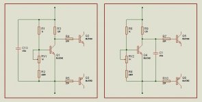
I think the capacitor should be the AC link between the VAS and it's current source/sink. The left diagram.
But others have said the capacitor should be across the bases of the output stage. The right diagram.
Two viewpoints.
Maybe careful experimentation and/or simulation to discover what the experiment should be trying to reveal.
But others have said the capacitor should be across the bases of the output stage. The right diagram.
Two viewpoints.
Maybe careful experimentation and/or simulation to discover what the experiment should be trying to reveal.
AndrewT
I didnt know D. Self talks about this (I need to get his book), but here is an analysis on the same by Hawksford, thought you might enjoy it (if you havent seen it).
If the cap is intended to speed up the base charge removal then it should be closest to the drive transistors (the right) but since the resistor is only on the order of 10 ohms I dont think it matters signficantly.
Thanks
-Antonio
Attachments
Thanks Mag,
I had read that before but forgotten about it. 1984 just predates D.Self.
I can't save the pdf.
Have you protected it in some way?
Anyone else know how to save the pdf?
I had read that before but forgotten about it. 1984 just predates D.Self.
I can't save the pdf.
Have you protected it in some way?
Anyone else know how to save the pdf?
Thanks Mag,
I had read that before but forgotten about it. 1984 just predates D.Self.
I can't save the pdf.
Have you protected it in some way?
Anyone else know how to save the pdf?
Right click link above and choose Save traget as..
Soon i will publish..... gimme a couple of days.
regards,
Carlos
Yeeeeeesssssssssssss!!!........
A powerholic like me will really love you more Uncle Charilie....
I hope this time the upgraded MKIII Hx will be tune up the way like Super A or even more better....
Rock on Uncle Charlie.....
Regards,
right click does not give "save target as".
But since I rebooted the PC the file - "save as" is now working again. The icon for "save" is still greyed out.
But since I rebooted the PC the file - "save as" is now working again. The icon for "save" is still greyed out.
Too many guys asking...i would like not to get back to this amplifier
But i cannot say no to so many folks that are sending emails.
I am already doing...will tune it even better.... sound will be better and different...more tube alike.
regards,
Carlos
But i cannot say no to so many folks that are sending emails.
I am already doing...will tune it even better.... sound will be better and different...more tube alike.
regards,
Carlos

- Status
- Not open for further replies.
- Home
- Amplifiers
- Solid State
- Dx Blame MKIII-Hx - Builder's thread