I use i led acid battery for both for my Riaa and Cd-rom drive, the led batteries beats different ac solutions by some margin.
But the batteries are sure not perfect, adding 10000uf Panasonic tc at the poles and a 150uf nicolson at the end of the wire makes the battery even better.
Yes, batteries do have to be bypassed -- they are "radiators" in the sense of an antenna by virtue of their physical mass -- and the interconnects pick up emi and rfi.
"DC is DC" seems rather reductionistic.
Have we considered that batteries have AC and DC impedance?
Here you go:
http://www.telepower.com.au/INT95b.PDF
This is for lead-acid batteries. Impedance is generally resistive between 10Hz and 1kHz. It becomes inductive above that. So, it's not constant, by any means.
I haven't found a test yet on other battery types.

More, from another site:
There are three frequency regimes to consider when dealing with batteries:
1. Ultra low frequencies. These are frequencies measured in inverse hours or days. In this regime the battery acts like you would expect it to. At low frequency a battery will act like a current source plus resistance. All of the energy transfer will be due to ion movement through the electrolyte and none will be due to surface charge or capacitive storage.
2. Medium frequencies, 1kHz to 1 Hz you are dealing in the regime of ion movement. If you are trying to pull a 10 mSec pulse out of a battery you will be accessing surface charge and capacitive storage, but also charge due to charges moving across the electrolyte. By the induced charge theorem a charged particle doesn’t need to move all the way across from one electrode to another to realize this energy, an ion with a charge of one unit will induce a charge on the anode of 1/10 of a unit as it moves 1/10th of the distance from the cathode to the anode. But these ions move slowly compared to the electrons in a wire, and this shows up as an increased resistance. The shorter the pulse and the higher current drawn the more the internal resistance of the cell will show itself.
3. High frequencies for batteries are above 1kHz. In this regime impedance is a better term than resistance because capacitance and inductance come to play. Many types of batteries are spiral wound, which introduces more inductance than flat plates would, and of course all batteries are capacitors, having parallel plates separated by a distance. If the current is drawn from the battery in a series of short pulses at high frequency strange things can happen. For example you can get crazy oscillations in a feedback situation such as a switching power supply. In these kind of applications a capacitor across the battery lets the battery move into a lower frequency regime.
Thanks Dirk and John for the tech info - most interesting indeed.
For people that like the "sound" of simple circuits with their often much lower PSSR, the influence of the power supply is generally much higher (including headamps) and adding series filters is a logical addition
If the voltage loss can be tolerated, I wonder if Cmultipliers would be beneficial, particularly if using one on each battery wire for better isolation?
Thanks Dirk and John for the tech info - most interesting indeed.
For people that like the "sound" of simple circuits with their often much lower PSSR, the influence of the power supply is generally much higher (including headamps) and adding series filters is a logical addition
If the voltage loss can be tolerated, I wonder if Cmultipliers would be beneficial, particularly if using one on each battery wire for better isolation?
I think any battery supply should be heavily bypassed with low ESR capacitors.
That is the main function of bypass capacitors, to supply the current to the devices requiring it, thus effectively lowering the power delivery system impedance at the required frequencies, the smaller caps near the power supply pins supplying the near instantaneous power requirements the rest acting as a bucket brigade filling the ones down stream, the actual PSU filling the larger bulk reservoir caps, as the PSU is slowest to react. Analogue isn't usually as bad as digital as it works at lower frequencies, but it is stil advisable to have a series of caps from small SMD (or small PTH, inductance being your enemy here, so small package minimum lead length) chip devices near the pins with larger values sprinkled aroun the board.
I'm looking to make up a 5 volt battery supply for a Hiface Two using LiFeP04 batteries.
Will the following work OK?
(using a LM2937ET-5.0 LM2937 Low Dropout Voltage Regulator)
It looks like the choice for batteries is between the A123 type suggested earlier in this thread, or these:
EV-Power | Lithium Cylindrical Cell LiFePO4 (3.2V/3.0Ah)
They also do a 5 Ah version that may be a better bet with the regulator.
And a charger from the same source.
EV-Power | Charger 6V/2A for LiFePO4 cells (2 cells)
I like the sound of the HiFace Two using four AA nimh batteries but it needs more 'oomph' and a bit of livening up. I've heard the JK SPDIF Mk3, and the Human Audio Tabla, that use LiFeP04 batteries and they do have a livelier presentation.
Hi - looks interesting what you are doing but you might want to consider that LiFePO4 batteries - as of today - have not been well investigated for float, i.e. continuous, charging.
I have asked around about this and e.g. batteryuniversity.com suggests that for now LiFePO4 batteries are treated like Li-ion batteries which are not recommended for float charging.
A quote from an engineer working at linear technology on Li-ion batteries & float charging:
" ... but "normal" LiIon batteries is not recommended to charge like that due to you get small charging/discharging going in and out due to temperature change.
This does wear a little on the pack, as LiIon batteries gets worn by charging/disharging regardless how small the current is (kind of eats the battey), thats the main reason you have C/x or time charge termination. ..."
I am, however, VERY interested in finding more information about this - would like to float charge LiFePO4 batteries myself - so if you/one of the other DIY'ers know/have a different experience I'd appreciate hearing about it.
However, to somehow blur the field, I have actually bought a couple of LiFePO4 batteries which comes with an instruction paper saying that they can be float charged at 3.45 VDC after being fully charged to 3.6 VDC ....
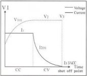
In case you are not familiar with charging LiFePO4 batteries it is normally recommended to constant current charge them up to a voltage (3.6 VDC) and after that a constant voltage charge until the current drops to 1/10 of the initial constant current charge value. I've attached an image of this.
Many ICs can do that, e.g. from Linear or TI.
Best regards,
Jesper
I have asked around about this and e.g. batteryuniversity.com suggests that for now LiFePO4 batteries are treated like Li-ion batteries which are not recommended for float charging.
A quote from an engineer working at linear technology on Li-ion batteries & float charging:
" ... but "normal" LiIon batteries is not recommended to charge like that due to you get small charging/discharging going in and out due to temperature change.
This does wear a little on the pack, as LiIon batteries gets worn by charging/disharging regardless how small the current is (kind of eats the battey), thats the main reason you have C/x or time charge termination. ..."
I am, however, VERY interested in finding more information about this - would like to float charge LiFePO4 batteries myself - so if you/one of the other DIY'ers know/have a different experience I'd appreciate hearing about it.
However, to somehow blur the field, I have actually bought a couple of LiFePO4 batteries which comes with an instruction paper saying that they can be float charged at 3.45 VDC after being fully charged to 3.6 VDC ....
In case you are not familiar with charging LiFePO4 batteries it is normally recommended to constant current charge them up to a voltage (3.6 VDC) and after that a constant voltage charge until the current drops to 1/10 of the initial constant current charge value. I've attached an image of this.
Many ICs can do that, e.g. from Linear or TI.
Best regards,
Jesper
Attachments
Last edited:
Thanks Jesper,
I had (perhaps naively) assumed that the charger recommended for these batteries would charge them in the appropriate manner.
If it is not clear in my diagram, the batteries would either be powering the HiFace, or being charged when the HiFace wasn't being used.
The Human Audio Muto DAC uses LiFeP04 batteries, and the manufacturer suggests that the charger can remain connected while the device is being used. Presumably that is the case with the HA Tabla as it is connected to the 5 volt supply of the computer whenever it is connected.
Hey Nuuk,
You're welcome - although I - as I hope I hinted at - hesitate to say that I "know" what could be the right/best way in this.
BTW that the chargers are connected while playing doesn't necessarily mean that they charge. Many ICs like e.g. LT3652 terminate charging after a certain time or 1/10 maximum charge current so they might not be active while playing. Some of them can also be actively set to be inactive under certain conditions.
Anyway, I was thinking that if you know just approximately how much current your circuits draw (HiFace) and can set a maximum charge current (at 3.6 VDC max) you can calculate the time needed to charge the battery & then give or take a couple of hours probably won't matter so much.
If you combine it with a under-voltage indication/protection (LiFePO4s shouldn't go under a certain voltage) or a timer circuit that switches off after a certain discharge time my best guess is that your batteries should be ok.
Otherwise - as I mentioned there's range of ICs available for this.
Regards,
Jesper
Jesper, I'm more confused than when I started! 😱
Are you saying that the charger that I linked to isn't actually up to the job of charging the batteries without extra electronics?
Are you saying that the charger that I linked to isn't actually up to the job of charging the batteries without extra electronics?
Jesper, I'm more confused than when I started!
Are you saying that the charger that I linked to isn't actually up to the job of charging the batteries without extra electronics?
Hi Nuuk,
No I'm not - actually, I can see that I didn't read your post in detail and so missed the link to the charger you were linking to. My apology for this - & for causing your confusion 😱
As it is your schematic may be ok. However, there might be some timing issues with the hiface electronics - i.e. that the voltage to the HiFace electronics must be present a certain time after the USB connection is established. I don't know since I am not familiar with the specifics for the HiFace Two.
Another issue could be that if you use a high value capacitor on the input of the regulator the switch you use would need to accept (very) high currents.
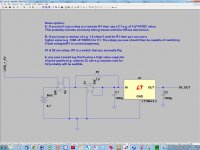
Thinking a bit more about it I've drawn up a circuit that might inspire you, (however, no guarantee it'll work as I don't know what's inside the Hiface, see above). I know there are also other ways of doing this but this is my suggestion as I reckon that you have a somewhat basic knowledge of electronics ... right?
First off - you might consider making the charger switch disconnect both the positive & ground wires - or disconnect the charger from the mains outlet when listening to your music.
Second - to make any charger circuit work you will need to disconnect the + 5VDC that the HiFace receives from the USB connection.
Then to the circuit: In this way the battery is only connected to the HiFace when the USB connection is also there. The first relay, S2, ensures this since it draws its current from the USB connection.
The simplest version is made of S2, a low value C1 (1uF), and a high value C2 (e.g. 1000 uF).
I took out the W1 switch but forgot to change the text - so please don't take notice.
The full version allows for a higher value of C1, which may/might improve sound (my guess would be that it does). C2 needs to be close to both the regulator and the HiFace.
If this is interesting to you I personally - before starting - would ask someone who knows about this if the HiFace electronics will accept a USB datasignal before the supply voltages are at their full value (& survive!). Both relays and capacitors have delays so I would make sure this is the case.
Good luck with your endeavors 😉
Best regards,
Jesper
Attachments
How does the noise performance of a battery + regulator compare to a standard DC supply + regulator? Since batteries cannot produce a regulated voltage, a regulator appears to be necessary for best linear performance of any circuit powered by them. Of course, the noise depends on which kind of regulator is used, but besides ripple in the standard DC supply, are there other noise sources in the standard DC supply + regulator that do not exist in the battery + regulator arrangement? It looks to me that a shunt regulator would be a bad choice for a battery powered device, since I think it would waste a lot of power and run the battery down faster.
Since no battery of anything other than ridiculous size has a near-zero impedance, no battery will ever be a "perfect" source of DC power for an AC circuit. At the very least some capacitor bypassing will be necessary. That's just basic electronics.
The only gain of a pure battery supply would be isolation from noisy AC power sources and ground loops, maybe... Lots more trouble than it'd be worth, to me.
Frankly, I'd be using lead-acid car batteries if it came to that. Cheaper and reasonably low impedance.
The only gain of a pure battery supply would be isolation from noisy AC power sources and ground loops, maybe... Lots more trouble than it'd be worth, to me.
Frankly, I'd be using lead-acid car batteries if it came to that. Cheaper and reasonably low impedance.
The LiFePO4 batteries have prettygood Zout, under 10mOhms , I won't be able to test them until we have power next wk
Surely if a HiFace Two is being powered by its own supply it wouldn't need the usb 5 volt supply, just the signal connection. There are usb leads out there without the supply wiring or you can just snip them out of an existing lead.
The Hi-Face is a digital inerface, that I presume works as is, otherwise people would not buy it, what improvement would operating it from a battery provide
The Hi-Face is a digital inerface, that I presume works as is, otherwise people would not buy it, what improvement would operating it from a battery provide
The same as any piece of hi-fi that has a better power source.
It sounds different when used on its own, with an Odysssey Audio TOD2, battery supply, or Paul Hynes SR-5 PSU.
- Home
- Amplifiers
- Power Supplies
- Anyone listened to Li-ion batteries?