Hi Rudi, I was far away for a few days, but when I arrived back yesterday late night I couldn`t resist and opened your envelope. PERFECT boards, PERFECT packaging. A very-very big thank you for your work!
Janos
PS: Witch company made this PCBs?
Janos
PS: Witch company made this PCBs?
@MADTECCHY: no it is not. I will send you a PM.
@Ronny: I like a PGA2311 based attenuator / source-selector very much.
It is not producing any audible "electronic smog" - even if you install it into the same case with the FC-100 - ,if it is carefully designed.
You can look for it either in this forum or ebay.
Best regards - Rudi
@Ronny: I like a PGA2311 based attenuator / source-selector very much.
It is not producing any audible "electronic smog" - even if you install it into the same case with the FC-100 - ,if it is carefully designed.
You can look for it either in this forum or ebay.
Best regards - Rudi
@Sir Rudi, I got the boards and all the components today. and as usual it is the finest quality anyone can have. Thank you very much for all of your effort Sir.
best regards,
Marjohn
best regards,
Marjohn
Sir Rudi,,I,ve received everything,,They are sooooo beautiful I don,t want to solder them So I think you should send me some more. You and Mr.Metal have done an outstanding job of doing this work to make these pcb,s truly a work of art. Evette
P.S. I,ll send you something in a day or soon for your review,,I,m sure your going to like it . Evette
Got the PCB today along with transistors, thanks. Now will wait for tx and emitter resistor. Thanks
Sent from my Galaxy Nexus using Tapatalk 2
Sent from my Galaxy Nexus using Tapatalk 2
Sorry, Gentlemen, the transformers do not fit into the coated letters that I have. I have ordered suitable cardboards.
The shipping of the transformers is therefore delayed by 2-3 days.
Best regards - Rudi_Ratlos
The shipping of the transformers is therefore delayed by 2-3 days.
Best regards - Rudi_Ratlos
use a bulb tester to save your transformer from damage. Determine the phasing of the primaries and mark the wires accordingly.
Determine the phasing of the secondaries and mark accordingly.
Determine the phasing of the secondaries and mark accordingly.
Andrew,
can You better explain your last post? Why do I need to know the phase of the primary and the phases of secondaries? For grounding issues?
And how can I determine that? Relative polarity of secondaries can be detected quite easily: if I put two secondaries in series, "counter-phase alignement" will yield 0 Vac, while "equi-phase alignement" will yield 68 Vac...
I imagine that should exist a better method, isn't it?
Thanks
Fabrizio
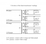
the two tappings for each winding are the same colour.
You must find which of the two ends match the corresponding ends of all the other windings. That is where we usually see a . (dot) used on the labeling and a colour code identifying that . (dot)
Take for instance a dual primary transformer without any phase coding.
For 110/120Vac mains power:
Wire the two windings in parallel but out of phase and the mains sees the primary winding resistance in parallel with the other primary resistance and when mains is powered on the transformer primaries draws hundreds of amps and instantly goes into NASA mode. The only thing that saves your transformer is the breaker back at the distribution board.
For 220/240Vac mains power:
Similarly wire the two secondaries in series but out of phase. The damage scenario is the same.
Use a bulb tester. The bulb will light if you wire the primaries wrongly. No damage. re-wire correctly, bulb stays off.
Now move to wiring the secondary. The out of phase secondaries when wired together will appear as a short across the two coupled windings. That again will damage the transformer if the distribution board circuit breaker does not come to your aid.
Use the bulb tester to prove you have wired the 4 secondaries correctly.
Why do we see so many not doing the research on the safe handling of transformers connected to mains power?
The information is spread around this Forum and repeated almost as often on ESP and yet we see Members asking the same questions "what are you talking about?"
Last edited:
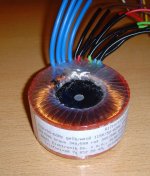
Gentlemen, the coloration - as is - of the transformer's leads has been requested by me.
Please have a look at the attached image.
You can see two secondary windings, with green and blue leads, labelled 1/2 and 3/4.
If you take a closer look, you can see that lead 2 starts as a blue wire ending in "green" and lead 3 starts as a green wire ending in "blue".
Connect the "blue-starting" leads 2 and 4 together resulting in 68VAC between the the green leads.
The same applies to the red and brown leads.
Connect the "red-starting" leads together resulting in 68VAC between the the brown leads.
Of course: use a bulb-tester before applying voltage to the transformer.
Best regards - Rudi_Ratlos
Attachments
Why do we see so many not doing the research on the safe handling of transformers connected to mains power?
The information is spread around this Forum and repeated almost as often on ESP and yet we see Members asking the same questions "what are you talking about?"
Dear AndrewT,
You are right! My ignorance is evident... 😱
And surely I will fill this gap quickly! I had never used bulbs in the past, despite I've read something about. But, for sure, I will, in the future. (Rudi describe it at page 7 in builder's manual)...
But don't worry that I never play with mains. I don't enjoy myself in taking risk by guessing. Safety is the first thing!
That's why I always use a fused and isolated variac (with Amp-meter) to power everything I start to build, and put extra fuses along wires during first startup.
Now, looking now at the shunt PCB I can see that two taps are connected together and connected toground (i.e. they are not "floating"). So When recognized that, my first question should be: how to connect the transformer correctly so that at "the opposite sides" of diode bridge flows 68Vac and not 0 Vac?
I can also understand that connecting two secondaries counter-phase will produce magnetic field cancelation, so that the coils behave like a short copper wire with catastrophic effects...
I promise that before start to working on I will be engaged with bulbs!
Kind regards
Fabrizio
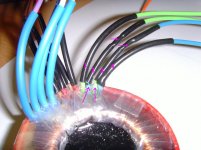
Fabrizio, have a look at my post #418.
The attached image shows you how to attach one shunt-regulator to the "green" and "blue" secondary windings.
Do not forget to manually solder the pink wires on the solder-side after you have finished the Shunt PCBs.
Best regards - Rudi_Ratlos
The attached image shows you how to attach one shunt-regulator to the "green" and "blue" secondary windings.
Do not forget to manually solder the pink wires on the solder-side after you have finished the Shunt PCBs.
Best regards - Rudi_Ratlos
Attachments
- Status
- Not open for further replies.
- Home
- Group Buys
- Roender's FC-100 Rev.1 Group-Buy