Rudi,
Your shipping charges are little higher than what you expected ?you charged me only 5.5 euro.But actual is 9.05😱😱
joshvi
Your shipping charges are little higher than what you expected ?you charged me only 5.5 euro.But actual is 9.05😱😱
joshvi
Hello Rudi,I received the package today.Top class.Also sent you ten euro for the extra postage.Kindest regards,Manuel
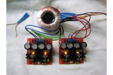
Received Shunt toroidal! very high quality... (as I thought)
My poor show with phasing secondaries was not funny, but was an useful lesson. Now I'm sure I will be able to correctly (and safely) handle this baby.
Thanks again
Fab
My poor show with phasing secondaries was not funny, but was an useful lesson. Now I'm sure I will be able to correctly (and safely) handle this baby.
Thanks again
Fab
Rudi, received the transformer today - very nice. Thank you. Also, like many others have noticed, the shipping was much more than you estimated and charged us. I will send you a Paypal transfer to cover the difference. You do more than enough to be out of pocket on these GB's. Jean
Received the transfo today as well
Extremely well designed transfo. Good quality!
I will add an extra 5 euros to you for the extra shipping
Thanks for everything
Do
Extremely well designed transfo. Good quality!
I will add an extra 5 euros to you for the extra shipping
Thanks for everything
Do
Gentlemen, please do not refund me any money!
My kitchen scales has shown me a weight of 480 gr incl. packaging, but the offical post-scales has shown 540gr 😱 !
I ordered a new kitchen-scales and will remember this expense and my mishap concerning the transformer's weight, when I do the next round
of group-buy for the beautiful FC-100 amplifier.
Best regards - Rudi_Ratlos
Last edited:
Shunt Transformer measurements
Rudi, completed the shunt PCBs and tested the transfo. Maybe should post this in build thread rather than GB anyway - results:
Transfo: 120 VAC in, Left:Out 1/2 39.4 VAC, 3/4 39.4 VAC
Right: Out 1/2 39.6 VAC, 3/4 39.6 VAC
PCB (No load or 2K Load doesn't seem to matter that much):
Left: Out + 37.2 VDC, - 37.3 VDC
Right: Out + 37.0 VDC, - 37.2 VDC
Note: Canadian Hydro is 120 VAC instead of 115 VAC
Attachments
Jean: this is exactly, how it should be! 🙂
Go ahead, please!
Best regards - I will keep my fingers crossed for your build - Rudi
P.S. I love your pictures!
Go ahead, please!
Best regards - I will keep my fingers crossed for your build - Rudi
P.S. I love your pictures!
Last edited:
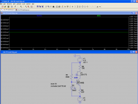
I have been asked to match 2SK170 - transistors for Mihail's FC-100.
The 1st image shows the LTSpice - model of my test-rig, the second image shows the result, when I measure the Vgs of a 2SK170 DUT.
LTSpice tells me to expect a value of about 80mV, but my DMM shows a value of 630mV.
The deviation should not be so big, and I think that the 2SK170-LTSpice model that I am using is "too rough".
Does anyone have a current LTSpice modell of a 2SK170BL?
Best regards - Rudi_Ratlos
Attachments
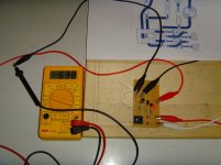
Hello Sir Rudi can you share the pcb lay out of the test rig, i need to much some 2sk170 for the fc-100.
regards,
marjohn
regards,
marjohn
the input jFETs operate over a range of current.
That range is determined by the level of input signal.
The two halves of the LTP should "amplify" the two halves of the signal they each see by the same amount.
That requires the jFETS to be matched over a range of currents.
Set up an LTP jig with the Sources connected together and the gates connected together.
Each drain connects to supply with 0.1%, or better, resistors.
Apply a fixed source current using the gate voltage as a trim. Measure the Vdiff at the drains. Sweep the source current and see how Vdiff varies. That is matching for use in an LTP.
This is quite different from selecting Idss for use in a B1.
I selected Idss in a matter of a dozen hours (600 devices).
Then, I matched the devices for use as LTP pairs. That took me hundreds of hours.
the input jFETs operate over a range of current.
That range is determined by the level of input signal.
The two halves of the LTP should "amplify" the two halves of the signal they each see by the same amount.
That requires the jFETS to be matched over a range of currents.
Set up an LTP jig with the Sources connected together and the gates connected together.
Each drain connects to supply with 0.1%, or better, resistors.
Apply a fixed source current using the gate voltage as a trim. Measure the Vdiff at the drains. Sweep the source current and see how Vdiff varies. That is matching for use in an LTP.
This is quite different from selecting Idss for use in a B1.
I selected Idss in a matter of a dozen hours (600 devices).
Then, I matched the devices for use as LTP pairs. That took me hundreds of hours.
I second that. It's not an easy job and took many hours to closely match jfets.
- Status
- Not open for further replies.
- Home
- Group Buys
- Roender's FC-100 Rev.1 Group-Buy