Have you spun out that power supply yet?
Inductance is quite low so you'll have to use large capacitance to end below 15mV.
Maybe a third filter step, a RC right after the rectifier?
Shoog, did you experiment with ultra low ESR caps on the multiplier?
I did not like it either with Rubicons on the John Linsley Hood circuit.
Did not try others but it tests superflat though 😉
Tried it once in a power amp and once in a preamp. Both times the same result - bloated sound with all top end fines robbed.
Didn't try Ultra-Low ESR, but just got the sound I needed with straight caps and a little bypassing.
Personally its CLC all the way for me now days.
Shoog
Same result here, thought it was because of the brand/type I used.- bloated sound with all top end fines robbed
Hang on a minute - why can't I bypass the input tube cathode resistor AND apply a L-W topology.
You can do that, by partial bypass. You only need enough unbypassed resistance in the input cathode to apply some noise cancellation. I'd try about 1/4 of the total resistance.
Or, you can use Darius's clever bootstrapped follower, if you are worried about input drive.
Loftin White: ECC83 300B Darius Loftin White Fortsetzung
Sheldon
Have you spun out that power supply yet?
Inductance is quite low so you'll have to use large capacitance to end below 15mV.
The noise cancellation is very effective. This is my headphone amp: http://www.diyaudio.com/forums/tubes-valves/125488-loftin-white-801-amp.html#post1551490 With this supply, more capacitance made no difference. Any residual noise I can barely see on the scope, I suspect is due to the filament heater (it's not Tentlabs low noise version). BTW, I would use DC on the filaments and Rod Coleman has an excellent version.
I used chokes that I had. Bigun can add some if needed. I'm not sure the low R supply will have the same effect as in conventional circuits. No harm in trying.
Sheldon
[1] and maybe I will also want to try 6C4C, 6P31S...
[2] and maybe I will also want to try 6G7, 6SF5, 6SL7...
It's helpful to read and understand this page, in setting conditions for the driver tube: Loftin White: ECC83 als Treiber für die 300B, Bestimmung einer Kennzahl
It's in German. The salient point is that the "triode characteristic factor" that Darius describes, should be 5 or more. Or put another way, the divider formed by the anode resistor and tube should be a factor of 5. The denominator, or resistance through the tube is (u times R cathode, plus R internal). Bypassing eliminates the first term and greatly reduces the denominator. I don't think your 300k anode load comes close to the factor of 5 with a 12AX7.
Note that the bootstrapped follower has a very high effective anode resistance, so neatly solves this issue as well as providing more oomph to drive the output grid.
Sheldon
Last edited:
I thought a bit more about my reply above, but didn't get it done in time, so here's the edit:
Link is in German. The salient point is that the "triode characteristic factor" that Darius describes, should be 5 or more to get good linearity and most of the u. Or put another way, the divider formed by the anode resistor and tube should be a factor of 5. The denominator, or resistance through the tube is (u times R cathode, plus R internal). Bypassing eliminates the first term and greatly reduces the denominator.
Let's take your 300k load at 1mA, and voltage of 200 at the plate of the AX7. You need about 2V at the cathode, so that means a 2k resistor. Ri is about 75k. The factor is 300k/((100x2k)+75k) or about 1. A bypassed AX7 would have a factor of about 5. If you play, you will find that not many tubes offer up convenient operating points. Because of the direct connection, all the voltages have to work together. It's work to get it right, but worth it when you do.
Note that the bootstrapped follower has a very high effective anode resistance, so neatly solves this issue as well as providing more oomph to drive the output grid.
Sheldon
Member
Joined 2009
Paid Member
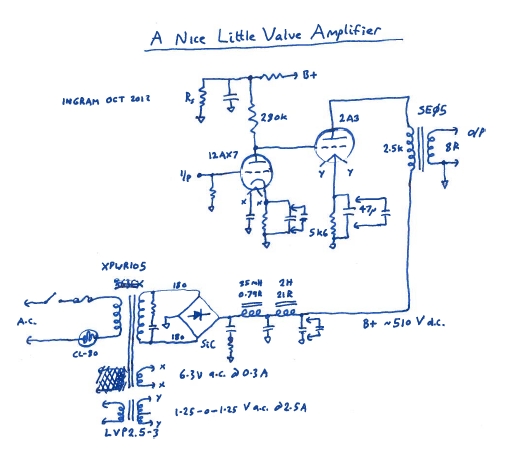
Disco - The power supply is unusual I'll grant that, but it's been used before by others (there's more chat over on Audio Asylum than here) and as you say, anything can be changed if it needs further work. Interestingly I also found other adherents to the idea - Sound Practices (issue 10) Diego Nardi of Audio Note "The HT supply for a Class A power amp, and especially for it's output stage, has to deal with a circuit modulating a large percentage of supply voltage and current if the amp is single ended. Therefore it is necessary to design a fast and nimble supply with short recover times, rather than one that stores a lot of energy. "
Sheldon - I don't think I need to leave any cathode resistance unbypassed at the input for the L-W noise cancellation to work.I am proposing a capacitive divider and with low impedances the frequency response of the divider is fine. The downside is the ability to fine tune - did you find that the noise cancellation was stable once dialled in, or did you have to reset it periodically ? and did you find that the null is very narrow or was there some range over which it was effective ?
The "triode characteristic factor" - just means sufficient anode load for gain and linearity - which for high mu tubes is always a challenge. With a bypassed cathode, 200V plate, -1.75V grid, a 12AX7 rp is 68k (reading off the graph in the data sheet from Sylvania), so applying x5 = 340k. I'm pretty close to that.
Bootstrapped follower - this is a nice trick, reminds me of my SS amps which all had the VAS load bootstrapped from the output. I could use the other half of a tube for that and still take the output from the anode of the first triode. I don't think we need it. Not only might the cathode follower add it's own flavour to the sound but I remember in the SS example that the quality of the bootstrap cap is important for the sound - we have in a roundabout way introduced a cap into the signal path that the L-W topology eliminates. Asano and Shishido didn't need it either.
I may later upgrade to dc filament but want to try it without first.
edit: just noticed your second post. I am using the 12AX7 at 0.6mA (Shishido uses 0.5mA, Asano 0.43mA, Don Garber and Dennis Fraker both use something similar). p.s. Google translate works well on Darius' blog.
Last edited:
Member
Joined 2009
Paid Member
Sheldon - I don't think I need to leave any cathode resistance unbypassed at the input for the L-W noise cancellation to work.I am proposing a capacitive divider and with low impedances the frequency response of the divider is fine. The downside is the ability to fine tune - did you find that the noise cancellation was stable once dialled in, or did you have to reset it periodically ? and did you find that the null is very narrow or was there some range over which it was effective ?
The noise cancellation depends on the u of the tube, which is very stable. In my experience it is narrow, but set and forget. If you are going to try it with capacitive dividers, I'd start low and start paralleling various sizes to dial it in. Not sure about this method though, I'll take a closer look at your proposal.
The "triode characteristic factor" - just means sufficient anode load for gain and linearity - which for high mu tubes is always a challenge.
Basically, yes.
Bootstrapped follower - this is a nice trick, reminds me of my SS amps which all had the VAS load bootstrapped from the output. I could use the other half of a tube for that and still take the output from the anode of the first triode. I don't think we need it. Not only might the cathode follower add it's own flavour to the sound but I remember in the SS example that the quality of the bootstrap cap is important for the sound - we have in a roundabout way introduced a cap into the signal path that the L-W topology eliminates. Asano and Shishido didn't need it either.
Some caps have more effect on the signal than others. This one will have a fractional influence - a lot less than a cathode bypass. Also, given it's size, a quality cap can be used. In the SS bootstrap applications I have seen, the cap is an electrolytic.
And yes, a current source would allow elimination of the cathode bypass too.
I may later upgrade to dc filament but want to try it without first.
Fair enough. In an earlier version of an 801Amp, I tried Steve Bench's method (also used by Darius), of canceling the filament noise. It wasn't easy, but that's with a 7V filament too. A good DC heater is easy. I have a low tolerance for hum, as I see no reason to permit it to exist.
I am using the 12AX7 at 0.6mA (Shishido uses 0.5mA, Asano 0.43mA, Don Garber and Dennis Fraker both use something similar). p.s. Google translate works well on Darius' blog.
One thing that Darius has pointed out in his blogs, is that early tube applications often used tubes at lower current than most modern designs, and with good results. It's not the stage that matters, it's the amp as a whole (and everything including the room, for that matter).
Do try this LF design, though. It works, and I find it quite elegant. It out aikidos Broskie.
Sheldon
Last edited:
The noise cancellation is very effective. This is my headphone amp: http://www.diyaudio.com/forums/tubes-valves/125488-loftin-white-801-amp.html#post1551490 With this supply, more capacitance made no difference. Any residual noise I can barely see on the scope, I suspect is due to the filament heater (it's not Tentlabs low noise version). BTW, I would use DC on the filaments and Rod Coleman has an excellent version.
I used chokes that I had. Bigun can add some if needed. I'm not sure the low R supply will have the same effect as in conventional circuits. No harm in trying.
Sheldon
You're referring to a LW-circuit but I was responding to this circuit:
Perhaps I can join in with that #50 LW, if I can find any 24 left.
Would a WE 259A do the trick instead?
Intriging circuit but would succes not greatly depend on tube wear?
You're referring to a LW-circuit but I was responding to this circuit:
Yes, with that more common directly coupled circuit, supply noise is not nulled, so more sensitive to ripple.
Intriging circuit but would succes not greatly depend on tube wear?
Actually no. It takes some work to get the right values for given tube types, but once set, it's self balancing. I've swapped tubes around of of varying age and performance with no issues at all. This may not apply when the tube weakens close to failing, but then it's time to replace anyway.
Sheldon
Bootstrapped follower - this is a nice trick, reminds me of my SS amps which all had the VAS load bootstrapped from the output. (But) we have in a roundabout way introduced a cap into the signal path that the L-W topology eliminates.
Let me add here, that if you are worried about cap influence, that the cathode bypass is far more "in" the signal path than the bootstrap cap. Any nonlinearity at the cathode will be multiplied by the u of the tube.
BTW, I'm not anti cap. My reason for using Darius's LW approach is the noise cancellation, and self balancing. It sounds great too.
Sheldon
Last edited:
Member
Joined 2009
Paid Member
When I saw the impact of not bypassing the input tube cathode resistor I decided that I would not implement the Darius scheme. However, after reviewing the comments from Broskie and realizing I could combine his idea with that from Darius I am now in favour of applying the L-W noise cancellation. I will build the circuit without it, but allow for the inclusion of it. Then I will include it and see what level of improvement it provides, along with any perceived tradeoffs. So, L-W is back on the table.
Sheldon - I see what you mean regarding the bootstrap cap - we don't need a large electrolytic in this case because impedances are much higher than in the SS example. It's certainly an easy experiment to try - I will have a narrow range of voltages to which I must elevate the heater on the 12AX7 so that both halves are within their heater-anode and heater-cathode ratings though.
Sheldon - I see what you mean regarding the bootstrap cap - we don't need a large electrolytic in this case because impedances are much higher than in the SS example. It's certainly an easy experiment to try - I will have a narrow range of voltages to which I must elevate the heater on the 12AX7 so that both halves are within their heater-anode and heater-cathode ratings though.
I will have a narrow range of voltages to which I must elevate the heater on the 12AX7 so that both halves are within their heater-anode and heater-cathode ratings though.
That's the tricky part with these, yeah it's tight but doable. If you set the grid of the 2A3 at about 110V (2A3 cathode about 160, B+ about 410), you can float the heater to about 80V and be covered for the full swing.
Or, separate heaters and envelopes for the input and follower. Or, if you don't mind an appropriate use of sand, a DN250 for the follower.
One thing to consider: You will push the tubes near their limits, and for a short time past them with your SS bridge. I use an indirectly heated (6x7 or 6CA4) hybrid bridge, so that everything comes up together.
Sheldon
You might want to check your load line on the 2A3. Your earlier schematic showed 45ma of current in the output stage. With a 5.6K cathode resistor, you'll measure about 252 volts. With a plate supply of 510, and a loss of ~4 volts in the OPT primary, 510-(252+4)= 254 volts cathode-plate. That's not a very good load line.
Also, some light reading on calculating bypass cap values, driver current vs slew rate and bandwidth, etc., should shed some light on basic design:
www.wavelengthaudio.com/bugle.pdf
Regards, KM
Also, some light reading on calculating bypass cap values, driver current vs slew rate and bandwidth, etc., should shed some light on basic design:
www.wavelengthaudio.com/bugle.pdf
Regards, KM
You might want to check your load line on the 2A3. Your earlier schematic showed 45ma of current in the output stage. With a 5.6K cathode resistor, you'll measure about 252 volts. With a plate supply of 510, and a loss of ~4 volts in the OPT primary, 510-(252+4)= 254 volts cathode-plate. That's not a very good load line.
No judgement here, but that's not far from a pretty typical load line for the 2A3. A little more current would probably be better. http://www.mif.pg.gda.pl/homepages/frank/sheets/049/2/2A3.pdf
Sheldon
No judgement here, but that's not far from a pretty typical load line for the 2A3. A little more current would probably be better. http://www.mif.pg.gda.pl/homepages/frank/sheets/049/2/2A3.pdf
Sheldon
No judgement taken. I guess it depends on your definition of far. The classic book spec is for 250V, 2.5K load at 60ma of current. The far in this case is 25% lower on idle current, or in reverse, the book spec calls for 33% higher idle current, that's pretty far in my view.
My preference (for the 2A3) is a 3.5K load, 300V at 55-58ma of current. It's more linear in it's load line, less distortion (measured) and better power with 4+ watts.
Regards, KM
Member
Joined 2009
Paid Member
I agree, when you look at the text book, it calls for a 2.5k load line as a the best compromise between power & distortion, along with Vp=250V and Ip=60mA. The reason I've shown a lower current is primarily to provide a good level of power derating for longer tube life.
It could get expensive on parts choices, but I would be at the front of the queue to wanting to try varying the operating point to learn how it affects the sound. I have enough headroom on B+ that I can push Vp up higher, primarily by stealing from the Vp of the driver. I could probably take Vp up to 290V if desired. I can also increase the current by adding another resistor in parallel to Ck without upsetting anything else.
The choice of OPT primary impedance is a hot topic for many, there are quite a few reports that say 3.5k is the best tradeoff, others say the traditional 2.5k is best. I have already ordered the OPT and it comes designed for 2.5k. I don't want to spend more $ on another OPT for this.
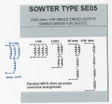
Now, I know there are compromises in doing this, but I can alter the reflected impedance of an 8 Ohm speaker at the primary by changing how I wire up the OPT secondary. The OPT secondary is an interesting design. Sowter recommend independent windings, no taps, for better h.f. performance. These windings are combined to suit the load impedance. They show connections for common loads. SE05 SINGLE ENDED OUTPUT TRANSFORMER
In the attached drawin I've added an additional wiring option which I believe provides for a 5.3 ohm speaker load. An 8 ohm speaker connected here would reflect back a primary impedance of 3.7k.
I've also attached the plate curves for the 2A3 and shown option 1) my current proposal, and option 2) a higher Vp, higher Ip and higher Zload. This last option would be feasible if using a JJ-2A3-40 with it's much higher power rating than NOS 2A3's.
Did I get these calculations *roughly* right ?
It could get expensive on parts choices, but I would be at the front of the queue to wanting to try varying the operating point to learn how it affects the sound. I have enough headroom on B+ that I can push Vp up higher, primarily by stealing from the Vp of the driver. I could probably take Vp up to 290V if desired. I can also increase the current by adding another resistor in parallel to Ck without upsetting anything else.
The choice of OPT primary impedance is a hot topic for many, there are quite a few reports that say 3.5k is the best tradeoff, others say the traditional 2.5k is best. I have already ordered the OPT and it comes designed for 2.5k. I don't want to spend more $ on another OPT for this.
Now, I know there are compromises in doing this, but I can alter the reflected impedance of an 8 Ohm speaker at the primary by changing how I wire up the OPT secondary. The OPT secondary is an interesting design. Sowter recommend independent windings, no taps, for better h.f. performance. These windings are combined to suit the load impedance. They show connections for common loads. SE05 SINGLE ENDED OUTPUT TRANSFORMER
In the attached drawin I've added an additional wiring option which I believe provides for a 5.3 ohm speaker load. An 8 ohm speaker connected here would reflect back a primary impedance of 3.7k.
I've also attached the plate curves for the 2A3 and shown option 1) my current proposal, and option 2) a higher Vp, higher Ip and higher Zload. This last option would be feasible if using a JJ-2A3-40 with it's much higher power rating than NOS 2A3's.
Did I get these calculations *roughly* right ?
Attachments

Yes, I'm quite familiar with the 2A3 plate curves. My main point is that running a lighter current (hence lower plate dissipation) will prolong tube life, but if you lower the idle current, it's better to increase to load impedance to improve the linearity (lower distortion) and get some additional power (better efficiency).
I have a stock of 60+ 2A3 tubes; RCA, Sylvania, Philco, Zenith, Ken-Rad, Tung-Sol, some original single-plate, typical twin with single plate and some true dual triode configurations (collected over 4+ decades... I'm pretty old). After exhaustive testing in multiple circuit topologies, I'm convinced that 3.5K is more optimum overall but you'll get the best overall performance by pushing them to ~16W of plate dissipation. I'm using older Tek, HP and Fluke test gear for all measurements.
You can also decrease the cathode resistor value and increase the current easily. And as you pointed out, you can re-wire the secondaries to change the impedance a bit. I'm also in the camp where my view on the input/driver is on the weak side. I built a pair of 45 SET amps years ago which use a similar topology to the Fi45 amp and uses the 6FS5. Nice sounding (MQ OPTs) overall, but they're just nice, not special.
Regards, KM
If high fidelity is paramount over efficiency, I'd recommend parafeed. Run the 2A3 with at least 100k plate load and the harmonics clean right out.
Put a gyrator on top of the 2A3, connect the OT to the MOSFET's source via a cap (4uF should suffice).
This has the benefit of sonically disappearing the OT, since there's no DC thru it. OT's generally seem to do much better with no DC.
Output power is slightly increased as well, with bigger voltage swing in 2A3.
- Home
- Amplifiers
- Tubes / Valves
- A nice little valve amplifier