Oh... A thought that crossed my mind regarding the 2M2 resistors from Gate to Source: When we say 'source' here, do we mean the JFETs pin called 'Source' or the way the signal is coming from, i.e. the input? 😕
I always mean "source" as in the actual pin on the FET.
For true JFET's the source and drain are interchangeable. In fact there is no way to determine one from the other as the device is symetrical.
For true JFET's the source and drain are interchangeable. In fact there is no way to determine one from the other as the device is symetrical.
I see. Is there a difference in ON and OFF instances in having the resistor connecting the Input-Gate or Output-Gate?I always mean "source" as in the actual pin on the FET.
For true JFET's the source and drain are interchangeable. In fact there is no way to determine one from the other as the device is symetrical.
(I guess the resistor plays a role only during ON times, right?)
The gate to source voltage is what determines the on resistance. That little bit extra voltage going from 0 volts to around +0.2 volts makes a big difference for some FET's.
I'll have to look back on some of your diagrams to see what you mean about the 2.2 m resistor... and I'm out of time tonight 🙂
I'll have to look back on some of your diagrams to see what you mean about the 2.2 m resistor... and I'm out of time tonight 🙂
I put 2.2ΜΩ from Gate to Source to all FETs, as I assumed from earlier posts. What I am wondering is if it is important if the JFET's Source (and hence the resistor) "looks" towards the input or the output of the signal... I hope you understand what I mean...The gate to source voltage is what determines the on resistance. That little bit extra voltage going from 0 volts to around +0.2 volts makes a big difference for some FET's.
I'll have to look back on some of your diagrams to see what you mean about the 2.2 m resistor...
Hope you have fun tonight! I am going out atm! 🙂and I'm out of time tonight 🙂
Such a pull-up resistor is not absolutely necessary. It can reduce distortion, but it is really only effective when it's in the tens of k-ohms range, in which case you need to drive the JFET switch directly from a very low impedance source (i.e., opamp output) or you'll get terrible control voltage feedthrough and thumping.
If this is for a musical instrument application then you don't need to worry about the distortion- it'll only be of the order of 1%, which would not be noticeable.
If this is for a musical instrument application then you don't need to worry about the distortion- it'll only be of the order of 1%, which would not be noticeable.
I see post #26 has your 2M2 resistors.
My answer is going to be 🙂 that unless I built and tested one of these switch elements using the FET's you have, that I wouldn't really like to say one way or the other although I don't really see the need for it either.
My answer is going to be 🙂 that unless I built and tested one of these switch elements using the FET's you have, that I wouldn't really like to say one way or the other although I don't really see the need for it either.
Thank you guys!
Merlin, yes, this is a guitar amplifier circuit.
Mooly, I ordered the components yesterday so I'll start building it at the end of next week.
😀
Merlin, yes, this is a guitar amplifier circuit.
Mooly, I ordered the components yesterday so I'll start building it at the end of next week.
😀
Mooly, I ordered the components yesterday so I'll start building it at the end of next week.
😀
A week off... wonderful 😛
Hello again!
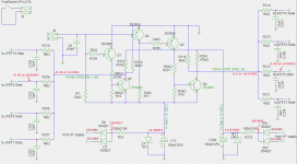
I built the circuit, and measured the voltages. I am attaching the file below.
Some observations:
1. As I understand the FETs cannot turn off completely with -4.2 VDC, right? Also, during the ON state the voltage at the Gate is +0.1VDC, as U can see from the schematic. Can't I just omit the 1MΩ resistor or increase the voltage before it?
2. Something that has me wondering is why I get from the V- rail supply only -8.49VDC, while the V+ rail has 14.87. (Does R7 have something to do with the voltage there?)
Thank you! 🙂
Attachments
I think I got it! By raising-finetuning the values of R202,R204, R218 and R219 I can get the Voltages I want for both states. I'll try it tomorrow and I'll post my findings!
Cheers!
Cheers!
Make sure that the zener stabilised supplies are OK under all switch conditions. I would have thought it better to rectify and smooth the HT first and then apply to the zener via a resistor or at least split the 150K witth a cap. You have to have -15 volts across the zener.
I only had time to run a simulation yesterday, but i found that it's the rest of the circuit that affects V-. Disconnecting the supplies from the rest of the transistors brought V- back to 14.89. Changing the 6k8 resistors to bigger values also raised V-, although I have to keep the ratio for keeping 0.2V. I'll try it tonight.Make sure that the zener stabilised supplies are OK under all switch conditions. I would have thought it better to rectify and smooth the HT first and then apply to the zener via a resistor or at least split the 150K witth a cap. You have to have -15 volts across the zener.
🙂
The supplies should hold up under all possible loading that can be presented.
The cap across the zener can't work as a reservoir cap because the zener clamps the peak voltage to 15v. As the AC cycle continues the voltage can only fall across the cap. If the cap were before the 150K then it would maintain a constant voltage (and hence constant current) across and through the zener. If you were to scope the 15 volt zeners I think you would see the supply isn't clean.
If you are simulating it then replace the zeners and their feed with a constant voltage supply (two 15 volt supplies) and get the circuit to work correctly from that 🙂
I just found this thread. I see that there has been considerable discussion regarding a fairly complicated fet based channel switching scheme for a guitar amp.
I use simple LDR's. It is a Cadmium Selenide photoresistor and an LED inside a sealed package. LED on... resistance is about 100 ohms. LED off resistance is about 10 meg ohm. They work good for channel switching. The resistance curve is not linear but they are good enough that you can make a channel transition with a pot based foot pedal.
Soldano used LDR's for channel switching in some amps (SLO100). They have one extra stage in the overdrive channel so that the channels are out of phase at the summing junction. This way any leakage cancels.
Soldano used Vactec VTL5C1 which are expensive. I use these:
Attachments
Has anybody used HEF4066 to switch audio signals.
According to the specification THD is just 0,04 % ( 0,5 Vpp in ) and isolation - 50 dB.
According to the specification THD is just 0,04 % ( 0,5 Vpp in ) and isolation - 50 dB.
Has anybody used HEF4066 to switch audio signals.
According to the specification THD is just 0,04 % ( 0,5 Vpp in ) and isolation - 50 dB.
Yes, and they can be very good. Best results are obtained when the signal voltage across the switch is kept at a minimum as would be the case at the input to a virtual earth mixer.
- Status
- Not open for further replies.
- Home
- Live Sound
- Instruments and Amps
- JFETs as switch in 2-channel tube amp