I listened to the F6 against the F5T extensively tonight. My setup is .15Rs with top cap connected bellow Rs and the bottom cap connected above Rs. My gain is 8 or 18dB. I will continue to play around with numbers and hope to post measurements, but the sound is enjoyable enough to me, where I will not be building any more amps for while. I have built 6 in the past year and while I have enjoyed them all, nothing has seized my attention like this one. Perhaps I like the romantic side of sound, dunno. I will build a J2, some variation of SUSY, and hope for the Sit's to be released. Only reason am doing that is to see if J2 is similar as well as how outstanding SUSY is. As for SiT, I remember Pass saying in SiT Nemesis article that the SS parts sounded flat compared to the SiT, with Sit having better separation and space.. I can't stinkin imagine how good they sound if these sound sorta flat. I am going to concentrate on other projects like my unfinished DACs, MY B5/B4 clone, my shiglaclone transport, and my speaks. If you don't try this amp, sorry! I gotta go bug ZM about proper speaks, preferably really expensive ones.Oh forgot, I started drooling when I thought about getting my 6V6 finished and in front of this amp.
Did you use BudPs transformers?
Thanks
Yes. I have not auditioned others, though. I have an ADC I need to try as well. May order the Jensen, but feel pulled more towards Lundahl. Its hard to ignore Nelson's recommendation, but BudP is in the business and does place great importance on the listening end as well.
@ZM,
ITs not like I dont like the glo plugs. They are very pretty
@ZM,
ITs not like I dont like the glo plugs. They are very pretty
if you already have BudP's iron , then no look further
you can try Jensens ( cheap enough) , as you can easily find good place for them (F6 for your Bro)
I didn't heard Onetics , but I have no doubts - man knows his biz , and he certainly worked with best in field
😉
you can try Jensens ( cheap enough) , as you can easily find good place for them (F6 for your Bro)
I didn't heard Onetics , but I have no doubts - man knows his biz , and he certainly worked with best in field
😉
Kinda what figured. Gotta ring him about some chokes for my 6V6 glow plug. I am starting to wonder if I "like that distortion"😀
it wasn't joke ;
there is difference between PSU choke and loading (anode or cathode or grid ) one .
even if I'm not in that woodoo and I don't know how to make one , I know that capacitance is what's important
there is difference between PSU choke and loading (anode or cathode or grid ) one .
even if I'm not in that woodoo and I don't know how to make one , I know that capacitance is what's important
More Teaser-6 adjustments. I received two more SemiSouth R100s and measures their transconductance along with the two R100s from the channel that wasn't performing as well.
New R100 JFETS
Gm = 9.335S, 8.046S
R100 JFETS from suspect channel
Gm = 7.203S, 8.282S
I paired the 8.046S and 8.282S JFETs and reassembled the PC board.
I finally found the "sweet spot" for lowering 2nd harmonic in this channel. It appears to be somewhere near Rs = R05.
I am listening to it now and the sound is better than ever. With pots in parallel to the source resistors, it is easy to adjust for your preference of harmonic content and level of global feedback.
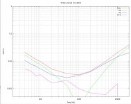
Here are the Harmonics vs Frequency sweeps for the two channels now.
As you can see, the 2nd harmonic is very low. The first plot is left channel that was previously the better one. The second plot is the newly configured and adjusted channel.
I still have no idea what harmonic balance and global feedback level Nelson is looking for.
New R100 JFETS
Gm = 9.335S, 8.046S
R100 JFETS from suspect channel
Gm = 7.203S, 8.282S
I paired the 8.046S and 8.282S JFETs and reassembled the PC board.
I finally found the "sweet spot" for lowering 2nd harmonic in this channel. It appears to be somewhere near Rs = R05.
I am listening to it now and the sound is better than ever. With pots in parallel to the source resistors, it is easy to adjust for your preference of harmonic content and level of global feedback.
Here are the Harmonics vs Frequency sweeps for the two channels now.
As you can see, the 2nd harmonic is very low. The first plot is left channel that was previously the better one. The second plot is the newly configured and adjusted channel.
I still have no idea what harmonic balance and global feedback level Nelson is looking for.
Attachments

Last edited:
Yup. The source resistors are 0R12. The pots are at about 40%-50%, meaning the modulation point is at about the equivalent of 50 mOhm.
Rs=50 mOhm ?
The pot adjustments perform 2nd harmonic nulling, similar to the of the P3 pot in the F5. They also allow the adjustment of the effective Rs values to anywhere between 0 and the actual source resistor which parallels the pot. See post #1844 http://www.diyaudio.com/forums/pass-labs/216616-f6-amplifier-185.html#post3164838.
Why not just kill Rs?
Yes I have tried it with the pots at 0. Look back at post #1951 http://www.diyaudio.com/forums/pass-labs/216616-f6-amplifier-196.html#post3168846 The difference in output impedance between that and Rs=0R05 is small, but the improvement in the distortion is significant. Basically, I have found a combination of the 2 pots that seems to minimize the 2nd harmonic pretty much everywhere, but particularly at mid frequencies. It probably also helps that I have matched the output FETs for transconductance.
I know. I am saying have you tried with no degeneration?
Last edited:
To whom are you directing that question? If me, I do not understand the measurement context. What AC voltage?
To measure AC voltage, did you just feed it 1V signal?
You don't need to remove the R100's, just measure the AC voltage Gate
to Source and compare it to the AC voltage across the source resistance.
At 100 Hz, a cheap ac voltmeter will do it.
😎
I was asking about this, I assumed you used it to match the transconductanvce of your fets. I was going to check mine.
Ok, now I understand the question.
I measured the JFETs in-circuit with a signal that gave a 4 volt peak output (1 watt). I measured the AC voltages gate to source and across the source resistor. I then calculated Gm = V(Rs)/(Vgs*Rs).
I unsoldered those R100s and tested them along with the new ones using my FET measurement setup using the same calculation and similar AC voltages.
I was asking about this, I assumed you used it to match the transconductanvce of your fets. I was going to check mine.
- Home
- Amplifiers
- Pass Labs
- F6 Amplifier