Have you ran a curve trace of both to see how closely they are complimentary?
Nope - only Id matched, but I wonder if close matching is worth the effort at all: I mean, if throwing in 4 randomly selected devices you get 0.0005% THD at the expense of a slight DC unbalance...
L.
Choco, i like the extension you made. If it sims well i would like to build a prototype.
Joachim,
I started to sim, but had no models of reasonable JFets.
After seeing silly results as a consequence of using silly types I decided to check for models of the 2SJ74 and 2SK170.
I have to ask for patience and cannot make promises on a time schedule.
Busy week ahead...
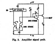
George Wilson presented an all NPN and NJFET op-amp in >>1968<< that had 200V/usec slew rate and 50MHz BW.
I never saw any followup
Attachments
Followup -
Maybe we could do it for him. RIP. Do the followup for audio.
I found it interesting that George Wilson presented an all NPN and NJFET op-amp in >>1968<< that had 200V/usec slew rate and 50MHz BW. This WAS potentially good for audio but I never saw any followup.
Yup, the same Wilson as in the current mirror.
Maybe we could do it for him. RIP. Do the followup for audio.
How much gnfb does it take to get below .001% ?
I have never, in my life time, had a hard time getting low thd in an amplifier. It just isnt that hard. If you have a symetrical and balanced circuit, it doent take much gnfb to have very low thd. I think i showed that with a measured .0005% thd + n with modest gnfb. Decades ago I had <.002% at 22 v p-p on the very first line stage I ever designed. That one had only 20db gnfb.
So, remind me again -- I am not sure what we are doing now for a discrete opamp design? What is it that we can do discrete better than an IC opamp? -Thx - RNM
linuxguru
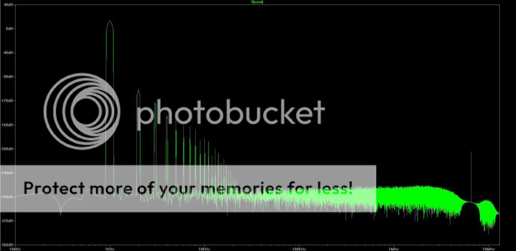
I think there's something wrong with your sim. The descending slope on the right might be caused by a LF drift in the caps, it's not always there anyway... The skirts round the fundamental don't look right either.
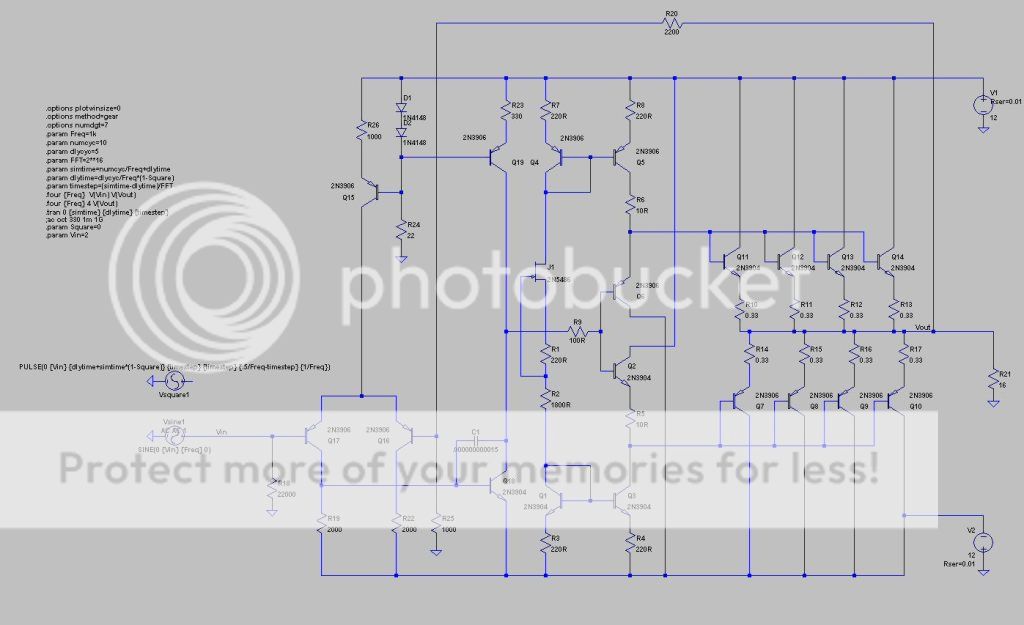
Spice directives for simulation courtesy of keantoken.
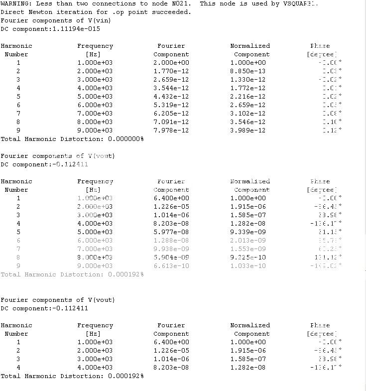
2V in, 6.4V out (peak) into 16 ohms, as shown. < 2 PPM THD. It's not the least number of components, but you can get these transistors for $0.03 ea. Surely that's got to count for something. 🙂
I think there's something wrong with your sim. The descending slope on the right might be caused by a LF drift in the caps, it's not always there anyway... The skirts round the fundamental don't look right either.
Spice directives for simulation courtesy of keantoken.
2V in, 6.4V out (peak) into 16 ohms, as shown. < 2 PPM THD. It's not the least number of components, but you can get these transistors for $0.03 ea. Surely that's got to count for something. 🙂
Damn. Thanks.
You'd think it would make more difference to the sim. I moved it and got 0.00016.
You'd think it would make more difference to the sim. I moved it and got 0.00016.
Thanks, Dimitri. As shown, Wilson's topology has a minor biasing problem for the 3rd-stage darlington, but that's easily fixed with a dual-diode in the emitter. The CCB can be grafted on for the O/P stage, but the darlington VAS won't be good for sonics, at any rate.
So, remind me again -- I am not sure what we are doing now for a discrete opamp design? What is it that we can do discrete better than an IC opamp?
As Scott has reminded us, the existing discrete opamps for audio run +/- 24 VDC rails for +24dBu output into 600 Ohms. No sense doing less. Class A output at that level isn't difficult either.
Some things not always clear in monolythic opamp performance are high frequency common mode distortion levels with high (maybe 10K Ohm or so) source impedance, clipping overload recovery behavior, and sensitivity to power supply imperfections. A truly hot dog design would address these things too.
Thanks,
Chris
Last edited:
Yup, known LTSpice artefacts from a quick-and-dirty 5-cycle transient simulation and Hann window. Not really a problem for getting a rough idea of the relative harmonics.linuxguru
I think there's something wrong with your sim.
BTW, I changed the upper cascodes to BF822/823, Miller caps to 10 pF and output NPN to 2sc945. Added 22k to ground at high-Z gain node, as suggested by Scott. GBW is up to 48 MHz, so all is well.
you can get these transistors for $0.03 ea.
Except the NJFs, all of my transistors run to maybe 5c each.
Of possible interest: the sim results for a perfect buffer compared to the one shown.Yup, known LTSpice artefacts from a quick-and-dirty 5-cycle transient simulation and Hann window. Not really a problem for getting a rough idea of the relative harmonics.
BTW, I changed the upper cascodes to BF822/823, Miller caps to 10 pF and output NPN to 2sc945. Added 22k to ground at high-Z gain node, as suggested by Scott. GBW is up to 48 MHz, so all is well.
A trick I used when playing with discrete CFA, but it seems a purely cosmetic effect, isn't it? Once OLG @ 20 kHz is fixed, I think there's no point in deliberately lowering it at LF just to get a flat OLBW - 120 dB @50 Hz and 70 dB @ 20 kHz is better than 70 dB from 50 Hz up to 20 kHz...
L.
You must have missed the controversy, some claim otherwise.
Yup, known LTSpice artefacts from a quick-and-dirty 5-cycle transient simulation and Hann window. Not really a problem for getting a rough idea of the relative harmonics.
BTW, I changed the upper cascodes to BF822/823, Miller caps to 10 pF and output NPN to 2sc945. Added 22k to ground at high-Z gain node, as suggested by Scott. GBW is up to 48 MHz, so all is well.
Except the NJFs, all of my transistors run to maybe 5c each.
The 22K to ground was a nod to those that think 20KHz open-loop BW improves things, what I'm not sure. This should probably be left for listening experiments.
Yes Dimitri, that's it. There is a full schematic in Cobbold's book from George's paper. Some real funky old school tricks to use only one flavor of device.
The 22K to ground was a nod to those that think 20KHz open-loop BW improves things, what I'm not sure. This should probably be left for listening experiments.
If I build a PCB, I'll bring the gain-node out to pin 8 as external compensation, assuming it's a single DIP8 implementation. Added bonus: people can use their favourite buffer and bypass the default internal buffer if they wish. The only hitch is additional track parasitics at what looks to be a critical high-Z node.
The old idea that a wide open loop bandwidth is a good thing got started way back when slew rate and TIM was the raging discussion and has lingered on in audio-lure as a design criteria. Some people think it sounds better that way.
So, if you do a pcb of Scott's circuit then you can compare - with the same exact circuit is best - low-medium and high gnfb by changing one resistor (maybe a pot or switch selectable) and then you can listen. That was one of my intents to try for.... To be able to listen to circuits - but all with super low thd -with various levels of gnfb. That should clear up the issue once and for all, don't you think? Thx - RNM
So, if you do a pcb of Scott's circuit then you can compare - with the same exact circuit is best - low-medium and high gnfb by changing one resistor (maybe a pot or switch selectable) and then you can listen. That was one of my intents to try for.... To be able to listen to circuits - but all with super low thd -with various levels of gnfb. That should clear up the issue once and for all, don't you think? Thx - RNM
Last edited:
Some real funky old school tricks to use only one flavor of device.
Aren't those p-channel FET's?
Thanks,
Chris
Yes, as one does when fabricating JFETs alongside NPNs.Aren't those p-channel FET's?
Thanks,
Chris
There are no PNPs to be seen on the full schematics. Maybe I will scan the section and post, since the book is long out of print. The discussion is good too.
Aren't those p-channel FET's?
Thanks,
Chris
yes. P-channel. All npn bjt. [Fig 10.29, pg 395]
Last edited:
- Home
- Source & Line
- Analog Line Level
- Discrete Opamp Open Design