Ricardo if you lover the current to half.. You loose a little gain, but not that much.. app. 6 dB, but considering the higher output of the more windings and the low noise of the circuit I don't see that as an issue....for you cart the lower current and a recalculated RiAA section may just be the right medicine.
The Paradise R2 has a noise impedance of around 7.5 Ohm. That is the Rbb` ( ca. 30 Ohm / 8 ) plus the 8 x 33 Ohm of the degeneration resistors. There is some 1/F but not much because we use bipolars. Your Denon has 40 Ohm, so even at half the current, the noise will be still dominated by your cartridges Johnson noise.
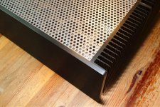
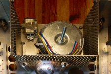
Let There Be Light!
Well almost...
Little fault finding on second be fun…
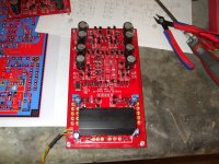
Both boards are stuffed
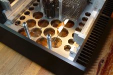
Board quality is top, easy to solder on and pretty sturdy, they do take quite a lot of abuse, even from inexperienced soldering irons, it is the first time I solder SMD and the by pass capacitors on the bottom went in real easy.
There are few points I am discussing with hesener but nothing stopping build as they are.
On off the minor moods, Just to give you taste of it, is around Neumann resistor, I don't know if I like it or not, so I have soldered a bypass switch straight on the resistor leads.
Once I heard it either may go...
Now may job being to be dumb...
What is the voltage it should be set out of the regulator Say TP102?
Is there a post about the voltages at the test point across the board?
By the way if you look at my part list same quantity for the components are short
Change the QTY for 150K 147k and 18K to 4
I had plenty of choice of matched pairs with the capacitors; some how they measure on the low side, but with the quantity I have ordered it was no problem making the 2 boards exactly the same.
Tanks Ricardo for posting the calculated RIAA values.
I think that I will find difficult to ear much difference but at least I know which way to go if I have to round things up.
For example I did not have enough 147 K so I used 165K And 511k Which I had in my draw this give me 67K instead of 73.5K
Ricardo posted the following in post 6150
Quote> for 33.3n I get 9.545kr, 11.42n and 65675r (instead of 73.5k)
They will be changed to 147K to keep things as on spec ASAP.
This is it for now, Got little 4 year old coming to stay for couple of days so I am already booked with Spiderman Lego set….
Well almost...
Little fault finding on second be fun…
Both boards are stuffed
Board quality is top, easy to solder on and pretty sturdy, they do take quite a lot of abuse, even from inexperienced soldering irons, it is the first time I solder SMD and the by pass capacitors on the bottom went in real easy.
There are few points I am discussing with hesener but nothing stopping build as they are.
On off the minor moods, Just to give you taste of it, is around Neumann resistor, I don't know if I like it or not, so I have soldered a bypass switch straight on the resistor leads.
Once I heard it either may go...
Now may job being to be dumb...
What is the voltage it should be set out of the regulator Say TP102?
Is there a post about the voltages at the test point across the board?
By the way if you look at my part list same quantity for the components are short
Change the QTY for 150K 147k and 18K to 4
I had plenty of choice of matched pairs with the capacitors; some how they measure on the low side, but with the quantity I have ordered it was no problem making the 2 boards exactly the same.
Tanks Ricardo for posting the calculated RIAA values.
I think that I will find difficult to ear much difference but at least I know which way to go if I have to round things up.
For example I did not have enough 147 K so I used 165K And 511k Which I had in my draw this give me 67K instead of 73.5K
Ricardo posted the following in post 6150
Quote> for 33.3n I get 9.545kr, 11.42n and 65675r (instead of 73.5k)
They will be changed to 147K to keep things as on spec ASAP.
This is it for now, Got little 4 year old coming to stay for couple of days so I am already booked with Spiderman Lego set….
Attachments
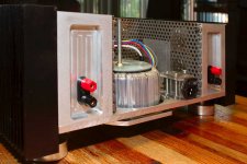
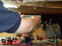
Just quick one
Second board up and ok Just silly capacitor wrong way round
hi, thats great news! from the picture it seems the amplifiers are not connected (yet), did you try and put the jumpers in (after checking VPLUS and VMINUS, the only two testpads with a name ;-) ?
I got Morgan Jones " Valve Amplfiers ", forth edition.
Again it is very entertaining to read, some things are new and some familiar.
There is more on BJT and Mosfet current sources and also JFet-Tube and BJT-Tube cascodes. There is a new line driver and a new BJT cascode, balanced Phonostage.
The authors Power Amps look a bit complex to me. I am certainly not in the mood to make a tube Power Amp. There is a lot about dynamic range, distortion and noise but i have not read the complete content.
Litle one is gone to wisit neighbours for a few minutes so small update.
as I said both boards up and running and yes got them connected nothing definitive so far just Oscilloscope trough passive anti RIAA they both loock fine.
So Just my one mistake with an inverted capacitor othervise it would have been they work fine from start for me as well.
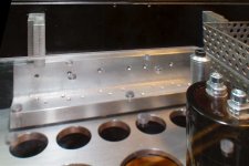
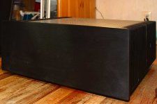
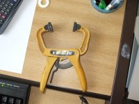
Just in case one strugle with heat sinks clamps for the TO220 I got solution to make thing child play.
PS I set V outs so to have 17.5 +- at OP amp pins
as I said both boards up and running and yes got them connected nothing definitive so far just Oscilloscope trough passive anti RIAA they both loock fine.
So Just my one mistake with an inverted capacitor othervise it would have been they work fine from start for me as well.
Just in case one strugle with heat sinks clamps for the TO220 I got solution to make thing child play.
PS I set V outs so to have 17.5 +- at OP amp pins
Attachments
Last edited:
Litle one is gone to wisit neighbours for a few minutes so small update.
as I said both boards up and running and yes got them connected nothing definitive so far just Oscilloscope trough passive anti RIAA they both loock fine.
So Just my one mistake with an inverted capacitor othervise it would have been they work fine from start for me as well.
Just in case one strugle with heat sinks clamps for the TO220 I got solution to make thing child play.
PS I set V outs so to have 17.5 +- at OP amp pins
grrrrrrrrrrrrrrrrrrrrrrrrrrrrrrrrrrreat!!!!
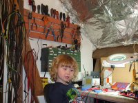
PS: loosk like the little one is getting the audio virus too......
Let There Be Light!
Well almost...
Little fault finding on second be fun…
Both boards are stuffed
Tanks Ricardo for posting the calculated RIAA values.
I think that I will find difficult to ear much difference but at least I know which way to go if I have to round things up.
For example I did not have enough 147 K so I used 165K And 511k Which I had in my draw this give me 67K instead of 73.5K
Ricardo posted the following in post 6150
Quote> for 33.3n I get 9.545kr, 11.42n and 65675r (instead of 73.5k)
They will be changed to 147K to keep things as on spec ASAP.
….
I would not change the 73,5k r for now (I believe these are ok because of the interaction of first mirror output imp and second stage buffer´s imput imp).... the most important values are 33.3n and 9549r because these will define the 500.5Hz point
Last edited:
As far as i can tell the Boboli has 1.5mV nominal output. Plus 20dB can be cut at certain frequencies so it will put out 15mV on the highest peaks. Say we have 60dB of gain, we end up with 15 V at the output ! The Paradise can throw 15V P-P so on the highest peaks it will just not overload but you end up with a lot of voltage before the preamp. The 150 Ohm may certainly need a coupling cap.
So I should use a coupling cap just to be sure the cart is not affected by input offset.... but what about the possibility of the paradise outputting 15V... what harm can that cause to the following preamp ?
Sorry, i thought that was DC offset at the output !
When the pamp has a potmeter at the input it will work. You just have to turn it down quite a bit.
When the pamp has a potmeter at the input it will work. You just have to turn it down quite a bit.
I repeat : The Paradise should not have much DC offset at the output but there can be a lot of AC voltage on peaks when you use a cartridge like the Boboli.
That will not destroy the following buffer or preamp but can overload the power amp.
So best you put a pot meter before the stage that follows the Paradise.
That will not destroy the following buffer or preamp but can overload the power amp.
So best you put a pot meter before the stage that follows the Paradise.
Ok sorry for the misunderstanding. Off course I will use a pot between the paradise and the buffer before the power amp.
As for imput offset, I will experiment with a DL160 that has similar output as the boboli and see what is the outcome before I go meet my friend 🙂
As for imput offset, I will experiment with a DL160 that has similar output as the boboli and see what is the outcome before I go meet my friend 🙂