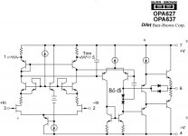
637 - Class AB Amplifier
OPAM 637 is very popular with the OPA structure is simple.
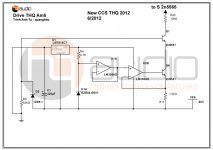
I'm inspired by it and the amplifier circuit diagram has the same structure to create this amplifier 637.
This is the inner structure of OPAM
OPAM 637 is very popular with the OPA structure is simple.
I'm inspired by it and the amplifier circuit diagram has the same structure to create this amplifier 637.
This is the inner structure of OPAM
Attachments
Last edited:
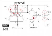
You have removed the LTP current mirror. Although I expec this design will work without it, loop gain will be lower and current balance in the LTP will not be optimum. Both of these will lead to higher distortion.
You have removed the LTP current mirror. Although I expec this design will work without it, loop gain will be lower and current balance in the LTP will not be optimum. Both of these will lead to higher distortion.
please see this mode OPA 637
Attachments


The voltage reference of the common base transistors in the cascode input stage is ground and not as in the 637.
The voltage reference of the common base transistors in the cascode input stage is ground and not as in the 637.
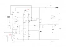
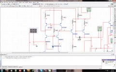
I changed them and test simulation software running on Mutisim.
a fun change, but pretty good results!
the constant current circuit diagram for the j-fet input, very little noise and running smoothly!
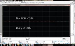
It is usually not much different in noise that can be seen in simulation of different CCS topologies. Worse, lower noise doesn't always mean better sounding. I'm still not sure if I want to go the trouble building such a complex current source. What is your experience. Is it a big improvement soundwise? I mean, are you just relying on simulation numbers?
ADD: Note that the amp would probably be using regulated front end supply
Last edited:
??????It is usually not much different in noise that can be seen in simulation of different CCS topologies. Worse, lower noise doesn't always mean better sounding. I'm still not sure if I want to go the trouble building such a complex current source. What is your experience. Is it a big improvement soundwise? I mean, are you just relying on simulation numbers?
ADD: Note that the amp already uses regulated front end supply
my experience is to practice many times,
and tested on actual measurements, tests by many people listen and compare!
current source I have is simple and I noticed not like, I want a smaller noise, so I need to change! I Want amplifier with parameters better technically.
It is usually not much different in noise that can be seen in simulation of different CCS topologies. Worse, lower noise doesn't always mean better sounding. I'm still not sure if I want to go the trouble building such a complex current source. What is your experience. Is it a big improvement soundwise? I mean, are you just relying on simulation numbers?
ADD: Note that the amp would probably be using regulated front end supply
I do not understand this sentence, you just tell me!
my experience is to practice many times,
and tested on actual measurements, tests by many people listen and compare!
current source I have is simple and I noticed not like, I want a smaller noise, so I need to change! I Want amplifier with parameters better technically.
I think removing the current mirror is not in line with the spirit of using such a complex current source for the LTP...? Any reason for removing those transistors?
I think removing the current mirror is not in line with the spirit of using such a complex current source for the LTP...? Any reason for removing those transistors?
you say about current mirror for different pre??
or other?
New CCS its is no good for it??
[/B]
I do not understand this sentence, you just tell me!
I mean, by looking at perfectionism in you, you might use regulated supply for the front end LTP. This regulated supply will help lower the noise so complex ccs will be less critical than if using no regulated supply.
[/B]
my experience is to practice many times,
and tested on actual measurements, tests by many people listen and compare!
What I want to know is if you have taken the trouble to "voice" the current source. I mean, have you listened and compared several constant current sources. If so, then good, I might try it out. I myself doubt if I can hear improvement because the power supply for the opamp itself will probably have negative effect to the amp.
you say about current mirror for different pre??
or other?
New CCS its is no good for it??
Why have you removed these 2 transistors?
Attachments
Why have you removed these 2 transistors?
me you want to menu simple it
Why have you removed these 2 transistors?
this
Attachments
You have removed the LTP current mirror. Although I expec this design will work without it, loop gain will be lower and current balance in the LTP will not be optimum. Both of these will lead to higher distortion.
yes i see it!
Thanks
Quanghao, the input stage to the OPA6x7 is not a conventional LTP. Notice the phase is actually reversed; the Jfet sources actually point up; they are P-channel. This could give nice advantages to the way compensation is applied.
There are ways to perform this phase reversal with an N-channel or NPN LTP (something like cross-comp) but I think these may cause stability problems.
It would be interesting to see if you can make it work with the same input topology as the OP6x7. Otherwise, the circuit is actually pretty conventional, if performing well.
- Status
- Not open for further replies.
- Home
- Amplifiers
- Solid State
- 637 Amplifiers