Agreed about the voltage steps. I only showed that to indicate the problem i was having. I use .05 on my N channel test. It seems to be related to available current in the circuit. Yours happens at much higher currents than mine, but you have also bypassed current limiter.
You can use another method to determine the large current oscillations,
Load ‘PNP Vbe-Ic' measure condition,
Change RC=4.55, Imax=4000mA,
Use a large current diode, insert '+' to E , '-' to C, and press 'GO',
It will measure the diode's V-I curve,
From form, observeds the 'Ve' column.
If 'Ve' value also unstable,The E Channel Amplifier is oscillation
Load ‘PNP Vbe-Ic' measure condition,
Change RC=4.55, Imax=4000mA,
Use a large current diode, insert '+' to E , '-' to C, and press 'GO',
It will measure the diode's V-I curve,
From form, observeds the 'Ve' column.
If 'Ve' value also unstable,The E Channel Amplifier is oscillation
Save the tabular data(.cuv), and upload them.Locky_z,
I did the test you suggested. Looks fine enough to me.
What next?
I need to read the data on 'Ve' column.
I tried this test using Mur3020WBT and was unable to get it to work
You can set less step voltage,
Save the tabular data(.cuv), and upload them.
I need to read the data on 'Ve' column.
I have linked the data here.
There are also P and N channel traces in the file for you to look at.
Hi Nic,attached as PDF. No zip tool on the Mac.
BTW: what is the easiest way to get the PC clipboard content into to posts on this forum?
You can use /usr/bin/zip on Mac, just open a terminal and run this command to zip up files, like "zip trace_data.zip trace_data.txt" will do.
From Windows, get a screen shot by moving the mouse to the window in focus, press <ALT> <CRTL> <PRT SCREEN> keys simultaneously, this will copy the screen shot into the buffer, you can then open paint and paste the screen shot into it. If needed, crop the portion that you want to post, save as jpg and upload.
Hope this helps.
Hi Nic,
Yes, paint comes with all versions of Windows (that I can remember). You can fire it up by typing "paint" in the run box or "Programs -> Accessories -> Paint".
One caution, typical Mac notebook keyboards don't have the <PRT SCR> keyword, at least not from my MacBook. If you are using Bootcamp to mutli-boot your Mac into windows, you will need to use an external KB, any 101 keys USB KB will do.
OT: spent a few days in Italy a couple weeks ago, lovely country.
Cheers,
attached as PDF. No zip tool on the Mac.
BTW: what is the easiest way to get the PC clipboard content into to posts on this forum?
I have observed these data 2SJ, Ve of the voltage is stable,
I think that the Vce=15V is too large.
When the current is greater than 3.5A,the voltage drop of RC may more than 3.5×4.55=16V,
System may hard to keep Vce=15V, and the curve is confusion.
You can set Vce=12V and try again.
Locky,
I have tried many different things with the P channel parts. Dropping the Vce has no effect on the outcome of my test. The only thing that allows it to test to 2500ma is to set the Vb steps high at .500mV. It is if the rapid step ups are robbing the bjt of current somehow. I have yet to be able to get the diode test to work either. I have tested the Diode using standard non linear IV curve without any trouble. Replacement parts should be here beginning of week.
I have tried many different things with the P channel parts. Dropping the Vce has no effect on the outcome of my test. The only thing that allows it to test to 2500ma is to set the Vb steps high at .500mV. It is if the rapid step ups are robbing the bjt of current somehow. I have yet to be able to get the diode test to work either. I have tested the Diode using standard non linear IV curve without any trouble. Replacement parts should be here beginning of week.
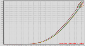
Ok. I exchanged both the LM568 op-amps with new branded LT1013 op-amps (LT1013CP from TI - beware that the LT1013 come in different packages!).
The curves now look better, but the tracer still "panic" at currents above 3.2A.
What to try next dear locky_z?
P.S. @Fred: thanks for the tip on how to attach images in Windows!
The curves now look better, but the tracer still "panic" at currents above 3.2A.
What to try next dear locky_z?
P.S. @Fred: thanks for the tip on how to attach images in Windows!
Attachments
Ok. I exchanged both the LM568 op-amps with new branded LT1013 op-amps (LT1013CP from TI - beware that the LT1013 come in different packages!).
The curves now look better, but the tracer still "panic" at currents above 3.2A.
What to try next dear locky_z?
P.S. @Fred: thanks for the tip on how to attach images in Windows!
NicMac,
Did reducing Vce affect your mesurements any?
The change of op-amps also seem to improve on the "interval narrowing effect", when measuring N-channel DUT's, but still not good enough.
I think locky_z would have a lot to gain (earn) by collaborating with us here at diyAudio so I'm sure he will come up with the fixes needed!
Cheers,
Nic
P.S. N-channel DUT in brown.
I think locky_z would have a lot to gain (earn) by collaborating with us here at diyAudio so I'm sure he will come up with the fixes needed!
Cheers,
Nic
P.S. N-channel DUT in brown.
Attachments
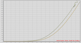
No. Here @ 12VNicMac,
Did reducing Vce affect your mesurements any?
Attachments

Last edited:
- Status
- Not open for further replies.
- Home
- Amplifiers
- Solid State
- DIY Curve Tracer for PC