Pinout of LF33CV will not fit , but LE33CZ will.There is LF33CV also. Found it better than LM2940-3.3.
Then LM2940 will not fit eitherLF33CV has identical pinout as LM2940
What I mean is that a big TO-220 type will fit if it has its ground leg on the outside not in the middle.Wchich type of regulator you're going to replace?
Hi,
Sure, go for it...
Ciao T
LM2940-3.3 is hard to get , but I can have
LM1117T-3,3 . What you think about that.
Sure, go for it...
Ciao T
Hi,
Sure, go for it...
Ciao T
Hi,
I did it. I put LM1117T-3.3 and got 3.3V in the output , but somthing weird happened.
There is a high frequency single tone noise audible in both twitters during a playback. And that's really annoing.
I don't know what I did wrong. What might have triggered that noise?
I really need your help here. If not fixed the player is totaly useless now.
Hi,
Regulator oscillating? Check datasheet for output and input cap requirements.
Ciao T
Hi,
I did it. I put LM1117T-3.3 and got 3.3V in the output , but somthing weird happened.
There is a high frequency single tone noise audible in both twitters during a playback. And that's really annoing.
Regulator oscillating? Check datasheet for output and input cap requirements.
Ciao T
And get ground from starpoint on the pcb, that is below the screw where the black ground lead is on.
And get ground from starpoint on the pcb, that is below the screw where the black ground lead is on.
I second the ground. Run the wire to the star ground for the regulator.
But with that little L78L33ACZ I had before it worked fine except output voltage was too low 2.97V.
I put oscons 220uF as ClefChef did , and wima 100nF from the legs to ground. The ground is 3cm away[negative leg of closest oscon] Maybe the oscons are to low ESR for the new regulator?Datasheets say 10uF tantalum for the fixed output regulator , but I guess that's minimum.
I put oscons 220uF as ClefChef did , and wima 100nF from the legs to ground. The ground is 3cm away[negative leg of closest oscon] Maybe the oscons are to low ESR for the new regulator?Datasheets say 10uF tantalum for the fixed output regulator , but I guess that's minimum.
Do you think that's necessity?And get ground from starpoint on the pcb, that is below the screw where the black ground lead is on.
As i said before the other reg. - L78L33ACZ worked with no trace of oscillation and noise, with the ground point 3cm away.
I had noise problems with some modifications. Often when a got a extra lead to the star ground the noise disapeared.
I got rid of that piercing noise[reg. oscillation]. That was not the ground problem Koifarm. That was the Oscon in the output. Too much of good thing. Too low ESR for that particular regulator. This is worth to read- Using 3-pin regulators off-piste: part 3 .Hi,
Regulator oscillating?
So I took that Oscon out and returned to the rubycon 100uF that was there before. No additional decoupling cups [100nF] are needed , there are two on the oryginal board already. The Oscon in the input seems to be ok. As the ground point for the regulator one can use the negative leg of the output cap as I did , it works good.
And I can recommend the mod , I like the sound , it's better.
Thank you guys for your advise.
Last edited:
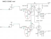
One of the problems that remains after MHZS opamp mod is done is too low output signal of the player. Much lower comparing with other players. The amplification of 12AX7 tubes is 100 times. So what we have here is either the signal is attenuated more than 100 times before output stage , or the output stage’ attenuation factor is less than 1 [0.8 or so] Can we do something about it with the existing schematic.
Changing 33k cathode resistor to 22k doesn’t make to much difference.
Is it possible that the signal was actually preattenuated in the dac digital domain? Did someone measure the signal after the dac?
The second possibility is that there is something like huge negative feedback applied in the tubes output stage shem.
Could some of you explain what impact on the signal makes that part of the schematic I circled in red? Does it work as negative feedback? What can be done here to lower the value of that nf? Will that help to make the output signal stronger?
Thorsten and Koifarm , what would you say about it.
Attachments
Last edited:
Do you mean this :Just look at first page photo 7 to change amplification.
"Replace the green 33K for 22k/1/4 Watt and replace the 68K for 82K/1 watt and the output signal is higher"
I should have said "amplification factor is less than 1".So what we have here is either the signal is attenuated more than 100 times before output stage , or the output stage’ attenuation factor is less than 1 [0.8 or so]
It is supposed to be :
So what we have here is either the signal is attenuated more than 100 times before output stage , or the output stage’ amplification factor is less than 1 [0.8 or so]
Yes, when you replace the 33k you can also try 27k. Some people had some distorsion with the 22k resistor.Do you mean this :
"Replace the green 33K for 22k/1/4 Watt and replace the 68K for 82K/1 watt and the output signal is higher"
First of all as I said couple of postes before I did change 33k resistor and that did not make too much difference as far as amplification is concerned.Yes, when you replace the 33k you can also try 27k. Some people had some distorsion with the 22k resistor.
Second of all my point is : what happens to that 100 times amplification factor of the 12AX7 tubes in that output stage. The amplification of the stage is not even 2 , it is actually probably less than 1.
So what part of the circuit is responsible for that. First is the very low anode supply voltage , but that's not enough to lower it[amplification] 100 times , so what else? My guess is that there must be some kind of negative feedback apllyed. I Suppose it is that part of the circuit I circled in red on the schem. Let's concentrate on that. Remember 100 times factor , not a fraction of one percent
- Home
- Source & Line
- Digital Source
- Modification of MHZS CD players