George obviously sells the Lightspeed but he doesnt try to sell it here, only describe it to DIYers and help them build their own.
"
Well everyone is happy then. 🙂 , as long as the same demonstrated freedoms including use of thread name, product names, avatars are available to all members.... and this is i think is a question for moderators to answer. 🙂
Cheers / Chris
,
Last edited:
Here are the DiY Audio Forum Rules for everyone about advertising:🙂
The regular forums are non-commercial and should have no advertisements or overtly commercial threads or posts. These belong in the appropriate Commercial Sector forums. Commercial entities may have threads and post in the regular forums discussing theory and initial product design. If a project gets close to commercial availability, the topic must be continued in a Commercial Sector thread.
Discussion of product design considerations may also be discussed by commercial entities in the regular forums, but promotion of specific products is not allowed. Members who want to start commercial threads may do so at no cost in the Vendor's Bazaar. Those who want more commercial exposure are encouraged to contact the management to discuss terms for obtaining a Manufacturers Forum or Vendor's Forum in the Commercial Sector. Banners and display advertisements are also available.
The commercial threads are for private transactions between members and other members or companies. diyAudio.com provides these forums as bulletin boards for the convenience of our members, but makes no warranty nor assumes any responsibility regarding unsatisfactory transactions. Customers can post any issue in the relevant thread to be answered by the vending party, as long as it is done in a civil manner. Normal diyAudio rules about member conduct apply and will be enforced. Please use the commercial sector bulletin boards at your own risk and using your own judgment.
How did I know a couple of days ago where this would end up.
The moderators are watching, please do not get this thread shut down.
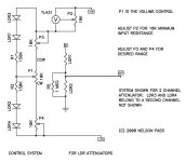
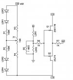
If anyone wants to try a different way of doing things, Nelson Pass spent a bit of time doing different things for the Lightspeed Attenuator a few years ago with no though of monitory gains and had my thanks and others as well.
Here are two ways he did things both had a buffer, I omitted it one of the diagrams.
Please feel free to use them personally, but remember they are protected and do not try to make them a financial going concern, as from what I've read and seen Nelson Pass does not like cloners who try make money on his designs, and he has the legal people to back it up.
Cheers George
The moderators are watching, please do not get this thread shut down.
If anyone wants to try a different way of doing things, Nelson Pass spent a bit of time doing different things for the Lightspeed Attenuator a few years ago with no though of monitory gains and had my thanks and others as well.
Here are two ways he did things both had a buffer, I omitted it one of the diagrams.
Please feel free to use them personally, but remember they are protected and do not try to make them a financial going concern, as from what I've read and seen Nelson Pass does not like cloners who try make money on his designs, and he has the legal people to back it up.
Cheers George
Attachments
It's best to remember that brief off topic is allowed here.
And moderation duties/ advice / guidance are best left to the moderators.
As a long time founder and moderator of another fairly large audio group that just celebrated 10 years, I can share something.
Moderators really don't want to interrupt good audio oriented discussion.
Usually, they only feel the need to do something when people start getting personal / attacking other people. As long as posting contributors are fairly focused on audio discussion, polite, or even somewhat impersonal, all is cool. Everyone is trying to contribute to the discussion, in their own way. Let it be.
And many thanks to George for posting his design, and contributing here over the long haul. It's a great design, which has spurred many innovations and offshoot designs. Most of which, were initially posted here in this thread. Very cool. 😎
Now, off to have some more green IPA 😛
I was thinking, but had not yet acted on Udailey's concern.
So I ask the question:
Is current control sufficiently different from the Lightspeed that detailed discussion of the topologies to achieve current control should be discussed in a separate thread?
I vote for a new Thread.
And ask for the relevant posts to be copied across to the new thread.
So I ask the question:
Is current control sufficiently different from the Lightspeed that detailed discussion of the topologies to achieve current control should be discussed in a separate thread?
I vote for a new Thread.
And ask for the relevant posts to be copied across to the new thread.
SPICE Model for NSL32SR3
.SUBCKT NSL32SR3 1 2 4 5
RIN 4 6 1
VT 6 5 0
GRES 1 2 VALUE = {V(1,2)/(97.7+(29970*((V(4,5))^1.5))+(0.1976/(V(4,5)))-(6780*(V(4,5))))}
.ENDS
.SUBCKT NSL32SR3 1 2 4 5
RIN 4 6 1
VT 6 5 0
GRES 1 2 VALUE = {V(1,2)/(97.7+(29970*((V(4,5))^1.5))+(0.1976/(V(4,5)))-(6780*(V(4,5))))}
.ENDS
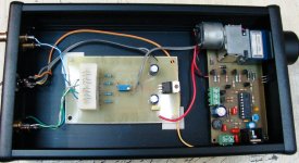
LIGHTSPEED attenuator conversion to remotely controllable unit. A quite easy work, just one 4.5mm hole on the front panel for the IR receiver.
PCB compatible with less expensive motorized potentiometer: BOURNS (Mouser price: 9.5 Euro).
Here the link for a detailed description of remote control unit: http://www.diyaudio.com/forums/analog-line-level/207419-remotely-controlled-motorized-volume-pot.html
Please don't take it as advertisement, schematics and PCB drawings and above all the program code in hex format (to be compatible with any type programmer) are offered FOR FREE.
Thank you!
Attachments

I think its pretty great and nice for you to provide the code for those that would like to build it themselves. This should work on any Lightspeed, original or DIY, that takes a 100k pot.
Good for me, much better for you! 🙂 The program code and the circuit are of professional level - tried and tested on actual devices 6 months so far without any problem - and may well be used in any commercial product. Anyway, since it was shared free, the code is "burned" IMHO. Despite all this, can be used in any project where the 4 basic remotely controlled functions (VOL+, VOL-, MUTE, STBY) are applicable. The brand and the value of potentiometer does not matters. Here the direct link to the project description and code in HEX:I think its pretty great and nice for you to provide the code for those that would like to build it themselves. This should work on any Lightspeed, original or DIY, that takes a 100k pot.
Matrix Multimedia user forums • View topic - Remotely Controlled Motorized Volume Pot.
Enjoy! 🙂
P.S. BTW, i have ready a program code for a mini remote control handset of high quality with just 4 buttons to complement the whole project. Exactly like this on the picture. No more use of remote control handsets cluttered from 20 or 30 or 40 buttons! I am in the process of drawing a new PCB, because recently i received samples of some last generation PICs and i feel obliged to try these. HEX code, circuit and PCB drawing, very soon available for free!
Last edited:
Glad it got to you safe and sound it's a long way from Australia to Greece, thanks for doing such a professional job on Johns new Lightspeed Fotios, he will be pleased when you forward it to him in freezing Norway, and if I decide to go remote with the production version I will be sure to contact you, it's far better than some of the rubbish available.
I have something in the oven for a Lightspeed Attenuator no expense spared version with your remote with contactless input switching, volume setup, balance and active unity/+6db gain buffer for those who need it or passive for the purists as it is now, contactless all the way through from input to output.
Cheers George
Recent notice indicates Cd in pro audio equipment analog circuits is exempt from RoHS till end of 2013. So it's good news.
Recent notice indicates Cd in pro audio equipment analog circuits is exempt from RoHS till end of 2013. So it's good news.
eh..? What does this have to do with Lightspeed Attenuator.
Glad it got to you safe and sound it's a long way from Australia to Greece, thanks for doing such a professional job on Johns new Lightspeed Fotios, he will be pleased when you forward it to him in freezing Norway, and if I decide to go remote with the production version I will be sure to contact you, it's far better than some of the rubbish available.
I have something in the oven for a Lightspeed Attenuator no expense spared version with your remote with contactless input switching, volume setup, balance and active unity/+6db gain buffer for those who need it or passive for the purists as it is now, contactless all the way through from input to output.
Cheers George
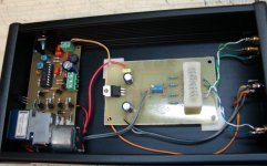
Thank you George. Oz to Greece distance is just 9 days. Parcel dispatched at 19 March and i received it at 28 March. And i live in north Greece, 600km far away from Athens. I did the modification with each respect to your work as you can see in pictures. I asked the LightSpeed to pass from my hands (it was a good oportunity, Greece is located at the middle of the travel from Oz to Norway) because i needed the case dimensions to draw the PCB to fit exactly inside Lightspeed.
Now the PCB layout is available for any DIYer.
Please feel free to contact directly with me in my e-mail address.
The same of course, for everyone else.
The LDR contains Cd.eh..? What does this have to do with Lightspeed Attenuator.
Hehe good to hear that Drama is actively creating awesomeness 🙂
I finished building Uriah's lightspeed version a few hours ago, now it s 3:30AM and I simply cannot stop listening to music... I just hope the neighbours do not call the police on me 🙂
Congrats George on an amazing idea. On my setup, it completely embarasses an ARC LS-25 and a Klimo Merlin.
Only issues for now are the expected non-mute lowest volume, the fact that I connected the pot the other way around and volume increaseas when I turn it CCW, and the steep slope that the volume increases.
I plan on handling them all very soon with a simple redesign of the pot circuitry that will even render LDR matching unnecessary. I won t say more now, I want to try a few things first before I publish my protoboards.
Fotios' solution is also in my todo list. I do not really like the idea of digital stuff in there, but the lack of remote volume is very annoying for me because I listen to music on weird hours and I change the volume very often so that I do not disturb the neighbours.
Anyway 🙂
I will post some photos once I manage to find some decent looking knobs 🙂
Dimitri
If you plan on some circuit to get rid of matching WOW that will be awesome! You must know that you can not just get the circuit to match them at one point and expect it to work from there on out. There are infinite points and the circuit must make up for the 'unmatching' at each point. I truly feel that a cpu is the only solution. Perhaps this is the route you are going or perhaps not. Good luck on it.
I could also see another circuit that samples the signal and matches to the signal on the other channel but you have to insert a stable signal into both channels to do this and then filter that signal out before it goes to the amp. DC would be the option here and this involves caps or a transformer in the signal which kind of kills the advantage of the LDRs.
Uriah
I plan on handling them all very soon with a simple redesign of the pot circuitry that will even render LDR matching unnecessary. I won t say more now, I want to try a few things first before I publish my protoboards.
The only simple re-design I can see is to use a balance control.
This could be easily adjusted with headphones and a mono switch/source (most of my FM tuners have a mono button).
Of course, remote control balance would be best, so you can adjust in your chair. A direct wired solution is probably not that hard if you are handy and use a source like "Small Parts" (now amazon supply) for shaft extenders pulleys, motor, etc AmazonSupply.com: The Hardware Store for Researchers and Developers
I also mentioned using a step attenuator with adjustment pots as needed at each step in the "other" LED/LDR DC bias thread that goes into this concept more.
The stepped way you are talking about I heartily agree with. Should work well but they still have to be moderately matched because when temp changes and they change resistance you want them to change in the same direction/rate. Also I wondered if people would put up with soldering 24 3 legged pots that cost about 84 cents each for each LDR. You might get away with 24 for each channel but it would also require a few more parts per channel. I just though its to much money and to much soldering for an enjoyable kit.
fit fixed resistors.
Then trim (by adding a parallel resistor) one or other of the pair to bring the LDRs to similar attenuation.
The trimming could be by using a variable resistor (1M0 or 2M2) and replace with a fixed once measured.
The big advantage of switched & fixed resistors, is the ability to choose the attenuation to suit the listening conditions.
You could have coarse steps from -1dB to -100dB or finer steps from -1dB to -30dB or again finer steps from -20dB to -50dB, or finally from -40dB to -80dB. Just get a ball park attenuation range that suit your equipment and range of listening levels. Then choose the fixed resistors to suit.
You could use a 3step attenuator:
background music / answering the doorbell.
listening attentively
party !
Last edited:
I would think a stepped attenuator that also selected the appropriate trim resistor at each position would make the match better since LDR curve shape may not be the same.fit fixed resistors.
Then trim (by adding a parallel resistor) one or other of the pair to bring the LDRs to similar attenuation.
The trimming could be by using a variable resistor (1M0 or 2M2) and replace with a fixed once measured.
The big advantage of switched & fixed resistors, is the ability to choose the attenuation to suit the listening conditions.
- Home
- Source & Line
- Analog Line Level
- Lightspeed Attenuator a new passive preamp