sorry!but topic is verry long!I cant find it!😀
You can thanks nazirdigi for pdf 🙂
You can thanks nazirdigi for pdf 🙂
i dont find the thanks????
Hi Apex,
Is c10 and r29 in parallel?will there be no problem if I connected d7 and d8 in supply and output.I noticed in your schematic it is in series with resistor emitter.
regards,
joel
Yes c10 and r29 is in parallel, and no problem to connected d7 and d8 in supply and output.
Replace C6 with 1000uF/16V instead 100uF.
Regards
Last edited:
thanks apex for the reply.
enjoy🙂
regards,
joel
Nice design,
regards
thanks apex for the reply.
enjoy🙂
regards,
joel
thanks your share
are you test??
not yet...
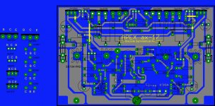
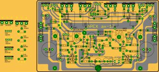
just check pcb if theres still something to edit just post and will change.
regards,
joel
just check pcb if theres still something to edit just post and will change.
regards,
joel
thanks drowranger
What is voltage supply for this amplifier,and what power it is?
Thanks for the files,great job! 🙂
thanks apex for the reply.
enjoy🙂
regards,
joel
What is voltage supply for this amplifier,and what power it is?
Thanks for the files,great job! 🙂
about supply...
hi,
its up to mr Miles dont know about the circuit and not yet try this board.but one advantage of parallel output is amp more stable at 4ohms.
Regards,
hi,
its up to mr Miles dont know about the circuit and not yet try this board.but one advantage of parallel output is amp more stable at 4ohms.
Regards,
I beleive that power supply voltage is higher than on ax14,just don´t know how far can it go with 4Ohm load at +/- 50V supply. Mile will appeare,he always does! 🙂
+-50Vdc supplies and 4r0 loading suggests ~200W for maximum output power.
I would go for a 2pair output stage with the total device Pd~600 to 800W, i.e. 150 to 200W per device.
I would go for a 2pair output stage with the total device Pd~600 to 800W, i.e. 150 to 200W per device.
What is voltage supply for this amplifier,and what power it is?
Thanks for the files,great job! 🙂
Rail voltage for AX17 is +/-45V
take a look at...
http://www.diyaudio.com/forums/soli...imate-fidelity-amplifier-123.html#post2948259
can you post pcb of the VU meter of post #182 or post #1224?
http://www.diyaudio.com/forums/soli...imate-fidelity-amplifier-123.html#post2948259
can you post pcb of the VU meter of post #182 or post #1224?
But there is pcb in post #1224
Just finished putting together AX17 as per post 1248. Replaced R13 with 2k pot to adjust DC offset to 0V. It works but for some reason can't adjust bias above 13ma (130mV across 10R instead of fuses) and Vbe on BD139 only 0.66V??? Checked everything twice and can't figure it out. Any ideas?
- Home
- Amplifiers
- Solid State
- 100W Ultimate Fidelity Amplifier