Due to a forum...ahem...action...which lost a post or two here, I feel I need to repost this one to help you follow the flow of AllenB's reply in #417 and hence participate more. 😱
I'm a bit disappointed that I seem to have got the transfer function for second order constant resistance series crossovers wrong. 🙁
An externally hosted image should be here but it was not working when we last tested it.
Wrong because AllenB's simulation doesn't come out flat:
An externally hosted image should be here but it was not working when we last tested it.
http://www.diyaudio.com/forums/multi-way/206843-sreten-speakerman-go-series-xos-40.html#post2936767
In fact, the Linkwitz-Riley type series seems to be doing the right stuff at the expense of constant resistance:
An externally hosted image should be here but it was not working when we last tested it.
Can you remind me what the coil and cap values are for that one, Allen?
Earl,
It is too sensible.
Series networks have no particular magic, nor are they useless.
Something I notice with all these crossover simulations seen in the last pages, they assume drivers that are flat DC to Light.
Real drivers have rolloffs and other non-flat response characteristics.
For example my ELECTRICAL first order series network is actually in reality a crossover that combines an ACOUSTIC first order lowpass (for at least 2 octaves) with a ACOUSTIC 3rd order highpass.
Equally, the modest mid-bass dip that is unavoidable in speakers that lack good directivity control in the bass (I know how to do it, I just lack time and funds for experiments) comes from the non-ideal behaviour of my midrange, which has a final 3rd order highpass function but is "transtitional" near the crossover point.
Ciao T
Why not worry about things that actually make a difference? Or is that just too sensible?
It is too sensible.
Series networks have no particular magic, nor are they useless.
Something I notice with all these crossover simulations seen in the last pages, they assume drivers that are flat DC to Light.
Real drivers have rolloffs and other non-flat response characteristics.
For example my ELECTRICAL first order series network is actually in reality a crossover that combines an ACOUSTIC first order lowpass (for at least 2 octaves) with a ACOUSTIC 3rd order highpass.
Equally, the modest mid-bass dip that is unavoidable in speakers that lack good directivity control in the bass (I know how to do it, I just lack time and funds for experiments) comes from the non-ideal behaviour of my midrange, which has a final 3rd order highpass function but is "transtitional" near the crossover point.
Ciao T
I can understand your misgivings with idealised crossover networks and idealised drivers, Thorsten, but from an engineering point of view you always try to create a mathematical model first. This basis seems to be lacking in series crossovers, and the peudo second order simple series filter is quite mysterious IMO.
We'll forever be stuck in mere opinion unless we get some sort of mathematical model, and AllenB and myself are working towards that even up to 2nd and 3rd order so far. 4th order is just technique, though I haven't tackled it yet. Lots of tricks with conjugates and source impedance may be applicable too.
It's proving quite hard and the algebra is frying my measly brain at least, but be patient. There may be a prize lurking in this rambling. 😀
Hi,
I disagree. Overly simplified mathematical models are overrated and under-performing to the point of being useless.
We now have by far more competent simulators anyway.
However, it would be trivial to model each driver as a 2nd order bandpass (an idealised driver is that) in addition to the crossover. Equally easy would be the addition of resonances and voice coil inductances.
This would be by far closer to a real crossover and actually would be able to show some of the more meaningful results.
I do not know recall where precisely, but I found mathematical treatment of series crossovers in quite old literature. It seems it is less the theory as such we are lacking, but coverage where it is easy to access.
Again, I find no use use for textbook models in reality, instead use real drivers as models and the use a competent simulator.
I hate to sound like a broken record. But this math is useless. Try modeling real drivers, real crossovers and include off axis simulations and test the real results. The Drivers need not to be too exceptional.
Ciao T
I can understand your misgivings with idealised crossover networks and idealised drivers, Thorsten, but from an engineering point of view you always try to create a mathematical model first.
I disagree. Overly simplified mathematical models are overrated and under-performing to the point of being useless.
We now have by far more competent simulators anyway.
However, it would be trivial to model each driver as a 2nd order bandpass (an idealised driver is that) in addition to the crossover. Equally easy would be the addition of resonances and voice coil inductances.
This would be by far closer to a real crossover and actually would be able to show some of the more meaningful results.
This basis seems to be lacking in series crossovers, and the peudo second order simple series filter is quite mysterious IMO.
I do not know recall where precisely, but I found mathematical treatment of series crossovers in quite old literature. It seems it is less the theory as such we are lacking, but coverage where it is easy to access.
Again, I find no use use for textbook models in reality, instead use real drivers as models and the use a competent simulator.
We'll forever be stuck in mere opinion unless we get some sort of mathematical model, and AllenB and myself are working towards that even up to 2nd and 3rd order so far. 4th order is just technique, though I haven't tackled it yet. Lots of tricks with conjugates and source impedance may be applicable too.
I hate to sound like a broken record. But this math is useless. Try modeling real drivers, real crossovers and include off axis simulations and test the real results. The Drivers need not to be too exceptional.
Ciao T
We'll have to agree to disagree then. 🙂
Mathematicians are good at spotting the pattern in a jumble of engineering results. This leads to insight, hypothesis, testing and new ideas.
Albert Einstein lamented that he wished he knew more mathematics, and I think you'll agree that general relativity was no sloppy piece of work. Us crummy audiophiles can't even agree whether valve amps have some secret sauce over transistor ones. So I reckon we're in the stone age here. 😀
I'll stick to maths, and can rely on AllenB (who knows a bit about speakers and filters) to do some simulations to test it. We're doing OK. We've already got flat impedance and flat amplitude as alternative design choices. That's progress.
Last edited:
Hi,
I have no disagreement with math. In fact, I wrote a few simulators in Excel that are or course math.
I wrote them mainly because I found the ones then in existence that used excessive abstractions and idealisations useless in practice.
I know I still sound like a broken record... Anyway, keep it real (math pun intended)...
Ciao T
We'll have to agree to disagree then. 🙂
Mathematicians are good at spotting the pattern in a jumble of engineering results. This leads to insight, hypothesis, testing and new ideas.
I have no disagreement with math. In fact, I wrote a few simulators in Excel that are or course math.
I wrote them mainly because I found the ones then in existence that used excessive abstractions and idealisations useless in practice.
I know I still sound like a broken record... Anyway, keep it real (math pun intended)...
Ciao T
When all you theorists who are basically re-doing what Rob Elliot and John K have already done (their work is linked in earlier posts), you will eventually come to the same conclusion as other theorists (i.e. build a series xo and measure it's performance).
Has ANYBODY bothered to click on the link I provided in post #411? I built one (3 component) for a high end 2-way and measured it. I have more measurements (off axis & phase). That is, if anybody is interested and cares to look beyond the math. 🙄
Has ANYBODY bothered to click on the link I provided in post #411? I built one (3 component) for a high end 2-way and measured it. I have more measurements (off axis & phase). That is, if anybody is interested and cares to look beyond the math. 🙄
I had looked at your link before. While it looks like it performs very well, it doesn't really show enough to argue one way or the other for series crossovers. It doesn't show the raw driver curves or the terminal volts so we don't know what the network is doing.
I have no problem with starting with idealized networks as long as the analysis eventually gets to real networks and drivers or even idealized but realistic networks and drivers. I suspect (as seems to be the case) that the starting point of ideal networks and resistive loads will show no significant differences between series and parallel networks.
If the differences are significant then you'll have to (eventually) get into more realistic sims to see it.
David S.
Yup, I looked at it too, and was pleased the link actually worked:
http://www.diyaudio.com/forums/multi-way/27969-series-crossover-9.html
Looks like something that might fry regular tweeters with a switch-on plop and make some serious demands of very high-end and expensive drivers. Interesting though. I like resistors in crossovers just for the nice amplifier load or source impedance, however you want to look at it. But I need higher order.
I don't know where this is all leading either. Neither does AllenB. But we're interested. For sure it's a nightmare trying to decipher the little literature we can find. But an open mind is best, no? You spannermen and grease-monkeys and us theorists who never get their hands dirty (allegedly...) should work together, eh? 😀
Attachments
I can understand your misgivings with idealized crossover networks and idealized drivers, Thorsten, but from an engineering point of view you always try to create a mathematical model first. This basis seems to be lacking in series crossovers, and the pseudo second order simple series filter is quite mysterious IMO.
Actually, the math of series crossover is trivial and has been well documented to the point that series crossover of order 1 to 3 were presented in an issue of Audio back in '78. I don't know why there is this insistence to rehash history. yes, I applied series x-o to a couple of designs for the purpose of making direct comparisons to parallel x-o's.
If you want to reinvent the wheel, fine. if you want to work through the simple math to learn something, fine. Just don't expect knowledgeable people to accept what you present as new or ground breaking.
It all comes off as you don't understand series x-o's, thus no one understands them. That is just arrogant BS.
This is akin to me presenting the derivation of impedance for inductors and caps.
Let's begin.
v = L di/dt,
i = C dv/dt
If i = I exp(st) and v = V exp(st) ,
di/dt = sI exp(st) = si,
dv/dt = sVexp(st) = sv.
Thus,
v = Lsi,
i = C sv.
Z = v/i
Z(L) = sLi/i = sL
Z(C) = v/sCv = 1/sC
For AC signals, s = jw.
All done. I hope you all learned something. Now that you understand impedance as well as I do you can all analyze any circuit you like. Or should I present a blurb on circuit analysis. Kickoffs laws, etc... Or maybe I should go back to kindergarten and learn how to place nice with others. 🙂
Last edited:
It all comes off as you don't understand series x-o's,
thus no one understands them. That is just arrogant BS.
Hi,
As is claiming they have universal panaceaic properties.
At least TL understands the fundamental reasons why
series can be better than parallel for 1st order electrical,
that great / near perfect drivers are not required for
series (though they usually help), and that the choice
of x/o topology is very much dependent on the drivers
parameters / responses and how they interact / are used.
Electrical filters in speakers hardly ever correlate to the
actual acoustic x/o orders or functions and analysing
resistive networks is totally missing the point*.
rgds, sreten.
*Well you can but its not very interesting. Its like trying
to use brainless x/o calculators to learn, doesn't happen.
Yup, I looked at it too, and was pleased the link actually worked:
http://www.diyaudio.com/forums/multi-way/27969-series-crossover-9.html
Looks like something that might fry regular tweeters with a switch-on plop and make some serious demands of very high-end and expensive drivers. Interesting though. I like resistors in crossovers just for the nice amplifier load or source impedance, however you want to look at it. But I need higher order.
I don't know where this is all leading either. Neither does AllenB. But we're interested. For sure it's a nightmare trying to decipher the little literature we can find. But an open mind is best, no? You spannermen and grease-monkeys and us theorists who never get their hands dirty (allegedly...) should work together, eh? 😀
No, nothing been's fried so far after months of playing. I call my speakers the 'Intimates' because they shouldn't be played loud. They are NOT designed for 100dB listening. They are designed for a small room, acoustice groups, female voice, classical quartets etc. I think you're kidding yourself if you going to design a 1st order series xo that's going to play very loud. You can search here for the holy grail of xo designs, but you won't find it. As you wrote, you need to go higher order for loud playing. BUT WHY INSIST ON THAT??? PLAY 'EM AT 75-95 dB range and ENJOY THE MUISIC!
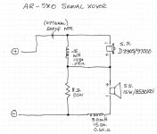
Where's AllenB when you need nim??? My schematic gives the perfect sim scenario!!!!! Those drivers I identified are well known with published imp. and FR files available. I GAVE YOU the xo components I found gave the flattest fr. What more do you want???
I guess the theorists here aren't interested either in my opinion on how they sounded, because nobody asked. 😡
Last edited:
The early Fried series designs from early 80's rated at 110-120 db it's on the IMF site. I have been using these designs for almost 30 years.
A single ended triode amp of 50 watts that I once used at a local dealesr does not produce enough current to play the satellites very loud.
The difference between the Dynaco ST-400 and Parasound Hca-3500 iwith the Frieds is amazing.
A single ended triode amp of 50 watts that I once used at a local dealesr does not produce enough current to play the satellites very loud.
The difference between the Dynaco ST-400 and Parasound Hca-3500 iwith the Frieds is amazing.
I guess the theorists here aren't interested either in my opinion on how they sounded, because nobody asked. 😡
And what are you going to say? "In spite of exceedingly flat response and my favorite series connected crossover the sound, unfortunately, sucked."??
The theorists are more interested in whether the topology offers any advantages in shaping the response of each section. We can come to our own conclusions on the resultant sound of our own designs.
We can come to our own conclusions on the resultant sound of our own designs.
So, it's two drivers and 3 xo components...... What's taking so long for somebody to put together a speaker, response shape to their heart's content, test it and share their results?
And what are you going to say? "In spite of exceedingly flat response and my favorite series connected crossover the sound, unfortunately, sucked."??
.
I will say they sounded a bit bright to me in my listening room, so I changed the xo to a capless SFE design (also 3 components) with a slight BBC dip which I'm still tweaking. Series xo's aren't necessarily my favorite xo. I just thought I'd try the AR SXO design concept and it seemed to work well with the SS drivers I chose. They handled power well and each had relatively peakless response profiles. I certainly understand sxo's aren't suited for all drivers like // ones are. It's much easier to add supplimentary response shaping and impedance management networks one generally needs with less than stellar drivers with // xo's
Speakerdoctor, this plot uses the wrong (but similar) drivers and the data is suspect. Find me some better data and I'll do what I can.
What does SFE stand for here?
Here is a link to the tweeter (D9500) files.
Driver FRD & ZMA files
I'll have to look some more for the 15W woofer/mid files.
Do you have graph tracing software? I understand there is some software that can somehow trace mfgr. published tests and convert them to .frd and .zma files. Can you do this? If so, then visit the SS site for their test results.
Last edited:
With tracing there'd be no Zphase information. No acoustic phase either. Could derive MP but no delay to meet the tweeter files or your box. Considering the time it takes to trace, is there a better option?
My, you're up early! Good morning tomorrow.
I thought all you would need is the .frd and .zma files to build the model. At least that is what PCD uses. What SW are you using?
SFE is my abbreviation for Sonus Faber Extrema.
I thought all you would need is the .frd and .zma files to build the model. At least that is what PCD uses. What SW are you using?
SFE is my abbreviation for Sonus Faber Extrema.
What the tweeter and woofer receive in the output of a crossover network is the vector of a sum . One driver is +45 one is -45 Both drivers rotate up and down in frequency. Combined the phase shift is zero. Both drivers are always 90 degrees apart.
This is vector addition. This is why they always sum flat. It does require the use of Resistors in most designs.
These designs do require a large listenig area to fully appreciate the sound. Listening to a woofer playing flat bass to 30hz in a small room is going to sound boomy.
This is vector addition. This is why they always sum flat. It does require the use of Resistors in most designs.
These designs do require a large listenig area to fully appreciate the sound. Listening to a woofer playing flat bass to 30hz in a small room is going to sound boomy.
- Status
- Not open for further replies.
- Home
- Loudspeakers
- Multi-Way
- Sreten & Speakerman go at series XOs