In many applications it would be nice to have a double C-core with a magnetc path length equalizing gap. This would combine the best of all possible core-types, but to my knowledge for low power there is no such thing. BIG transformes built up of "stripe-packages" cut at an angel and precisely grinded to get wedge-type airgaps that equalize the flux have been built.
In output-transformers the 4:1 window of the M-core allows for less interleaving and givs shorter outside winding length than the usual 3:1 window of the EI core. But if gapping is needed EI is easier and more stable. In its usable range as a OPT, a M-type C-core outperforms EI,SE,UI,SU,M,and MD as well as standard "toroids" wich come with a small, but widely fluctating gap.
I therfore suggest to use the MD-core only for "upgrading" M-type transformers if
M-type C cores are not avaiable.
May be this is worth to mention also, the Waasner laminations are propable high silizium content. This is a very brittle and tool wearing stuff and it is hardly suitable for wound toroids or C-cores. Higher silizium content means lower eddy current losses at the same lamination thickness. The lamination is cut at a point where the flux is much lower than in the main direction and therefore the cores strays are very low as are the losses. Id
say, technically, this core will certainly beat most of the toroidial stuff floating nowdays around.
say, technically, this core will certainly beat most of the toroidial stuff floating nowdays around.
Even the smallest air gap will add more reluctance to the path than the iron itself, even if the outer path were twice as long as the inner path, the flux would be within 20% with a reasonable gap.A core with 2 magnetic paths has advantages over a core with only 1 magnetic path because a split magnetic path has smaller inner to outer magnetic path length difference at the same core-width. This givs the MD-core a advantage compared to the toroid. Furthermore the MD-core "window" coppercontent is in a totally different leage no industrial wound toroid could ever compete with.
the reasons they do that is so that they can fit grain oriented iron together such that there is no flux crossing the grain. you can read about this in detail in the P&J transformer book. and after slicing the core it is heat treated, there is no grinding except to remove burs.In many applications it would be nice to have a double C-core with a magnetc path length equalizing gap. This would combine the best of all possible core-types, but to my knowledge for low power there is no such thing. BIG transformes built up of "stripe-packages" cut at an angel and precisely grinded to get wedge-type airgaps that equalize the flux have been built.
I do not know what you mean by the 3:1 window you speak of but any increase in the copper to iron ratio will also increase the leakage flux. if that is not a problem then of course it is reasonable to increase the window area for specific reasons.In output-transformers the 4:1 window of the M-core allows for less interleaving and givs shorter outside winding length than the usual 3:1 window of the EI core. But if gapping is needed EI is easier and more stable. In its usable range as a OPT, a M-type C-core outperforms EI,SE,UI,SU,M,and MD as well as standard "toroids" wich come with a small, but widely fluctating gap.
I therfore suggest to use the MD-core only for "upgrading" M-type transformers if
M-type C cores are not avaiable.
My .003" inch thick laminated, three phase C cores which work fine at 1.5T and 400Hz don't have as much silicon in them as the 1960's E core i extracted out of a 1960's era phonograph when i was 12 years old-a core that would glow red hot if inserted into a 1.5T 400hz field.May be this is worth to mention also, the Waasner laminations are propable high silizium content. This is a very brittle and tool wearing stuff and it is hardly suitable for wound toroids or C-cores. Higher silizium content means lower eddy current losses at the same lamination thickness. The lamination is cut at a point where the flux is much lower than in the main direction and therefore the cores strays are very low as are the losses. Id
say, technically, this core will certainly beat most of the toroidial stuff floating nowdays around.
anyways, if you want very low eddy current loss but can deal with lower fields there's a few companies that make iron cores specifically for the 1000-18000Hz range, better than iron powder which at a permiability of 25-100 is a pain to even use as a transformer, but much higher losses (and power density than offered by ferrite) than the negligible "iron" loss at that frequency with ferrite.. which is limited to ~.3T
i'm not sure if the elephant in the room is the fact that every toroidal core i've unwound is actually ~20 strips of iron, each strip wrapped around the core 3-6 times with a small air gap between each strip. yes, i know, when you plug in a toroidal core you can watch the 100 amp turn on spike decay to the .1 amp magnetizing current after ~30 cycles, but its not like they are a bunch of "washers" punched out and stacked on top of each other, and instantly saturate at the slightest provocation.
Johansen
Even the smallest air gap will add more reluctance to the path than the iron itself, even if the outer path were twice as long as the inner path, the flux would be within 20% with a reasonable gap.
The fact remains that 2 magnetic path will have a better ratio of inside to outside magnetic path length, this applies also for cores with a small gap despite the equalizing effect oh the airgap.
the reasons they do that is so that they can fit grain oriented iron together such that there is no flux crossing the grain. you can read about this in detail in the P&J transformer book. and after slicing the core it is heat treated, there is no grinding except to remove burs.
I think I it made clear that stripes are used to build the core-blocks and therefore the flux will be in the direction of the grain orientation. What I wanted to tell is that there are BIG cores made (german manufacturer) that use a wedge-grinded airgap to equalize the flux. The weigth and material savings in the finished cores are considerable if compared to the standard cores you tell me to read about.
to be continued
Johansen, the core with grinded and optimized airgap is a product of E. Blum Kg in germany.
They claim a reduction of 6.8% in corelosses compared to a core of similar material using non grinded stripes. The comparison is made at a average flux of 1.75T wich is the recommended flux at 50Hz for those cores.
They claim a reduction of 6.8% in corelosses compared to a core of similar material using non grinded stripes. The comparison is made at a average flux of 1.75T wich is the recommended flux at 50Hz for those cores.
Johanson, as by your own words YOU DO NOT KNOW what I mean by 3:1 window ratio let me explain:
A 3:1 ratio means the window area is 3 times as wide as it is high.
For example a window would be 9cm wide and 3cm high giving a area of 27 square-cm.
The same window area with a ratio of 4:1 would be 10.4cm wide and 2.6cm high.
Since the more stetched out coil would reqire less layers the Rac losses at higher frequency are reduced when compared to the shorter coil. We also get a reduction in
leakage inductance and leakage flux. I you go further in "streching" out the coil you end up using a UI-type or even toroid type of core, wich allows for least interleaving, lowest leakeage inductance and strayflux, ac-losses a.s.o.but (among other things) at the penalty of only ONE and longer, thicker, magnetic path with naturally higher flux at inside compared to outside, it is peak flux what counts, not average.
Core-manufacturers know that, it is the reason why they specify different shape cores
(made of the same material) at different max average flux levels.
It is all about trade off that has to be made, especially in audio wide band transformers.
To compare a 0.00.3" C-core to a propable 0.13" EI-core with unknown properties and running it at 400Hz at a unknown fluxlevel and then stating it went red-hot is silly.
Thanck you for your well ment advice of looking into the core materials you mention.
I am familiar with them, special knowledge of all sorts of inductive components used in all sorts of applications has been part of my life. One of the biggest challenges has been as a consultant to ABB helping them to improve one of theyr inductor design for a 10MVA power inverter. It used originally the biggest iron powder pot-core I have ever seen and was water cooled. It was used in the GTOs snubber to regain the energy that usually only gets resistively dissipated. I made a watercooled and mica isolated coil
out of squared tubing for replacement of the pot core. Because of limited space I took the risk of a shorter multi layer coil instead instead of a much bigger 1 layer coil. It turned out that he loss induced heath was to high at the coolants pressure level. I went to parallel coolant feeding but the then necessary connectors blew up. Before that also stray-induced cabinet arcing and heating was also a problem. My final suggestion was to build a thick and short 1-layer air-cored toroid with multiple welded on water connections on the outside where flux is at minimum. I did not have the means to produce such a coil in my worksop so it was up to ABB to produce such a coil. I do not know the outcome but I am sure they managed the production difficulties.
As to the "elephant", lol, I gladly never came across a toroidial core made up of short stripes, I presume they are only a "invention" from very small transformer winders cutting the core from sheets to save costs.
yeah that's what i figured, and the 4:1 is going to have a higher leakage flux than 3:1, but that generalization generally fails because the depth of the stack is also a variable. if you stick to a square core or in the case of large distribution transformers, a circular core profile, the longer the window the more leakage there is.Johanson, as by your own words YOU DO NOT KNOW what I mean by 3:1 window ratio let me explain:
A 3:1 ratio means the window area is 3 times as wide as it is high.
For example a window would be 9cm wide and 3cm high giving a area of 27 square-cm.
The same window area with a ratio of 4:1 would be 10.4cm wide and 2.6cm high.
see this image for what i mean, and a window area ratio of 6:1 without interleaved coils can often be used for impedance protection, such as neon sign transformers.
http://www.vias.org/matsch_capmag/img/matsch_caps_magnetics-816.png
The leakage flux also induces eddy current in the conductors themselves, which may or may not be a concern to you.
Less resistance yes, because there's more copper, when you interleave all the coils to kill the leakage inductance the only thing that changes is the ratio of copper to iron.Since the more stretched out coil would require less layers the Rac losses at higher frequency are reduced when compared to the shorter coil
If you can make the case that a 4:1 ratio is better than 3:1 for whatever specific purpose, then i'm interested in knowing why not stop there? and then again, what is the optimum core cross section ratio? square, 2:1? 4:1?
Take the difference for example, between a toroidal transformer, and its analog, the pot core, both on opposite ends of several compromises.
yes, hyperbole of course but what you said was that older higher silicon content laminations which had supposedly less eddy current loss but also lower peak flux were better than the higher flux alternative.To compare a 0.003" C-core to a propable 0.13" EI-core with unknown properties and running it at 400Hz at a unknown fluxlevel and then stating it went red-hot is silly.
I'm sure you're aware that leakage and stray inductances follow the inverse of flux squared due to the relationship with turns squared.
Leakage flux will also increase with the flux density but the increase allows you to reduce the volume of both the core and the wire..
It is a compromise as you and I have stated...
Are you sure? i thought i differentiated between the toroidal coils cut from sheet metal (like a stack of washers), and toroidal coils which are wound from the proper electrical steel. In the latter case every core i've unwound (to make custom sizes) has multiple strips, each making 3-6 turns around the core, presumably to increase the air gap, otherwise it would effectively have none. Are you saying that respectable toroidal cores are wound from a single strip of steel?As to the "elephant", lol, I gladly never came across a toroidial core made up of short stripes, I presume they are only a "invention" from very small transformer winders cutting the core from sheets to save costs.
Last edited:
yeah that's what i figured, and the 4:1 is going to have a higher leakage flux than 3:1, but that generalization generally fails because the depth of the stack is also a variable. if you stick to a square core or in the case of large distribution transformers, a circular core profile, the longer the window the more leakage there is.
see this image for what i mean, and a window area ratio of 6:1 without interleaved coils can often be used for impedance protection, such as neon sign transformers.
http://www.vias.org/matsch_capmag/img/matsch_caps_magnetics-816.png
The leakage flux also induces eddy current in the conductors themselves, which may or may not be a concern to you.
I thinck we are talking about different things here. A wideband transformer, such as a OPT is hardly used near maximum flux. Core flux leakage is hardly a concern. What is of concern is to minimice leakage between primary and secundary, and the reduction of eddy currents (this is what i said, i said
that TO MINIMIMIZE Rac!) by choosing THE IN THIS RESPECT more favourable 4:1 window ratio, or even go to the extreme of a toroid.
The impedance protection you mention has nothing to do with that. This type of protection can be achived by winding primary and secondary side by side, inserting a magnetic shunt a.s.o. Only your imagination is the limit on how to introduce it.
It boils down to this, the longer coils, the less leakage INDUCTANCE between them. Offcourse a long coil demands a long core, and offcourse a core operating near maximum flux will have a COREFLUX STRAYFIELD that is of concern in a distribution transformer. Wideband transformers dont even care is there a core or not at the higher end of theyr frequency band. It is the coils that count and how tigth is theyr coupling. And the layerthickness
dictates the Rac that will result. Longer coil means lesser or thinner layers
and lower currentdensitie in the area where skin/proximity losses occur means lower losses.
Am am somehow tired to quibble with you about stuff that i said and you seemingly deliberatly misinterpret. Show a bit more of goodwill and may be this turns into something fruitfull.
It boils down to this, the longer coils, the less leakage INDUCTANCE between them. Offcourse a long coil demands a long core, and offcourse a core operating near maximum flux will have a COREFLUX STRAYFIELD that is of concern in a distribution transformer. Wideband transformers dont even care is there a core or not at the higher end of theyr frequency band. It is the coils that count and how tigth is theyr coupling. And the layerthickness
dictates the Rac that will result. Longer coil means lesser or thinner layers
and lower currentdensitie in the area where skin/proximity losses occur means lower losses.
Longer cores, required for longer coils, mean longer magnetic path length too.
With longer magnetic path length however the primary inductance will suffer compared to a shorter core (same core area and number of windings).
Not a completely free lunch therefore; to reach the same inductance on a longer core more windings are required leading to higher capacities.....
Longer cores, required for longer coils, mean longer magnetic path length too......
Pieter.
This is not an attack against what you have posted. I simply quote it because it is a good example of 3 "longer" that are being confused by at least me and seemingly a few others.
Too many "longer".
For the winding, surely the layer is one wire thick or for a 2layer winding, two wires thick.
For the width of the layer, it should be the number of wires laid side by side.
For the length of the winding we should be measuring the wire length used to wind around the core, times the number of turns in that layer.
When referring to magnetic path length, the longer is in a different direction to the longer (of winding) just defined. I see it as the path length around the core that the flux has to travel to get back to the start point for the measurement.
As for longer in respect to core, I don't know what this could be.
Window area and window shape: Let's define what we mean.
Hopefully all confusion will disappear if we agree on what we are actually discussing.
Last edited:
OK,
Here are the most important abbreviations used in "magnetics" and known to people who are into the matter:
- lfe = mean iron path length (yes mean path length around the core);
- Afe = net iron cross-sectional area (not the same as height x width!);
- Mfe = mass of iron core;
- ha = height of winding space;
- ba = width of winding space;
- lcu = average length of coil winding (average length of one turn);
- Acug = geometrical copper cross-section (ha x ba).
Source: "Strip wound cut cores" by Vacuumschmelze.
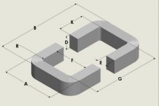
Which in books written in English might more often appear as:
F = window width [cm]
G = window length [cm]
MPL = magnetic path length [cm]
MLT = mean length turn [cm]
Ac = effective iron area (D x E) [cm^2]
Wa = window area (F x G) [cm^2]
Wtfe = iron weight
Wtcu = copper weight
F = window width [cm]
G = window length [cm]
MPL = magnetic path length [cm]
MLT = mean length turn [cm]
Ac = effective iron area (D x E) [cm^2]
Wa = window area (F x G) [cm^2]
Wtfe = iron weight
Wtcu = copper weight
Attachments
Of course there is no standardization in terms.
Ikoflexer: effective iron area is not D x E but about 80 - 90 % of that product (depending on core size).
Ikoflexer: effective iron area is not D x E but about 80 - 90 % of that product (depending on core size).
Longer cores, required for longer coils, mean longer magnetic path length too.
and lower magnetizing current as well....😀
Which in books written in English might more often appear as....
Well, the Vacuumschmelze "Strip wound cut cores" is also in English as the title already suggests 😉
F = window width [cm]
G = window length [cm]
MPL = magnetic path length [cm]
MLT = mean length turn [cm]
Ac = effective iron area (D x E) [cm^2]
Wa = window area (F x G) [cm^2]
Wtfe = iron weight
Wtcu = copper weight
"ha" and "ba" are more accurate parameters.
F and G are geometrical core dimensions; F and G do not take into account the loss of space by the bobbin.
For example, for an SG89/51 double c-core Vacuumschmelze specifies ha being 20,1 mm, whereas without bobbin there is 22,2 mm of space.
^well said Gorgon53, i agree with what you expounded re OPT's....🙂

Thanks Tony
Longer cores, required for longer coils, mean longer magnetic path length too.
With longer magnetic path length however the primary inductance will suffer compared to a shorter core (same core area and number of windings).
Not a completely free lunch therefore; to reach the same inductance on a longer core more windings are required leading to higher capacities.....
Sure pieter t, no free lunch ever, it is all about compromises. But the 4:1
rated window is still on the short side and will hardly be to long for a audio OPT. The capacity-thing....
The squared effect of the lower voltage/turn of a longer coil givs smaller effective capacitance dispite that more windings are required. The more stretched out coils outside-diam/inside-diam ratio is of advantage.
Less Rac copper losses, less interleaving, less capacitance between layers.
Less interleaving, higher voltage between layers, higher effective capacitance.
Choose your poison ;o)
Anyway, high BW does not really leave to much choice, the coil has to be stretched out more than the EI 3:1 window allows. This is one of the reasons M-cores where introduced in the first place. To be more "universallly" usable
than what allready existed and surely never was intended for audio use.
You clearly get higher BW and lower Rac-losses with the more stretched out coil despite the fact that you need more windings (as is easely confirmed by the high BW toroids can achieve).
- Status
- Not open for further replies.
- Home
- Amplifiers
- Power Supplies
- Core lamination