Congratulations!
Your choice of transistors is excellent ....except for the 2N3442 of course. I could hardly believe my eyes when I saw the Ft of 80KHz (No no, it's actually the Ft, not the cut-off frequency!).
The 2SA970's are excellent devices, and you have to thank them for the silence of your circlophone.
Your choice of transistors is excellent ....except for the 2N3442 of course. I could hardly believe my eyes when I saw the Ft of 80KHz (No no, it's actually the Ft, not the cut-off frequency!).
The 2SA970's are excellent devices, and you have to thank them for the silence of your circlophone.
looks good... may be i can plan to make this as my first solid state amplifier... Is it AB class operation amplifier.
looks good... may be i can plan to make this as my first solid state amplifier... Is it AB class operation amplifier.
This is very friendly amp for a first time solid state amp. Maybe the last 🙂. There is no biasing and thermal tracking issues which will became a nightmare for an unexperienced diyer. Highly recommended.
It looks superficially like class AB, but in fact it is not.Is it AB class operation amplifier.
This is an unconventionnal topology, and it doesn't fit into the usual classification system.
Calling it pure class A would be an exageration, yet it is closer to class A than anything else.
One could call it sliding bias class A, or dynamic class A, or energy-saving class A, or similar.
It looks like class AB, because there is a quiescent current, ~200mA and the current consumption increases with the output power.
But in reality, things are somewhat different.
The circuit is basically that of a beefed up JLH, with the phase splitter and the input stages implemented in LTPs rather than single transistors.
Except of course the initial bias current is too small to allow for full power operation. But when the instantaneous power increases, so does the quiescent current, because the currents in each arm of the PP are constantly monitored and processed to generate a quiescent current always 200mA higher than what is required to operate in class A.
In a conventionnal AB PP, the OP devices are left to themselves to decide how the currents crossing happen: it depends on the exponential B-E characteristic, the emitter degeneration, etc.
In the Circlophone, the crossing is under the active control of the small signal servo circuit, forcing class A operation.
A graphic illustration of that feature is that you can replace the CFP's OP by darlingtons or even MOSFets, without modifying anything in the circuit.
Elvee said:Congratulations!
Your choice of transistors is excellent ....except for the 2N3442 of course. I could hardly believe my eyes when I saw the Ft of 80KHz (No no, it's actually the Ft, not the cut-off frequency!).
The 2SA970's are excellent devices, and you have to thank them for the silence of your circlophone.
My skills are not capable design such circuits but my diy enjoyment generally related with testing different parts in unique designs. That's why I choose different transistors with Circlophone. I plan to build actual parts also but trying some different makes better enjoyment.
A graphic illustration of that feature is that you can replace the CFP's OP by darlingtons or even MOSFets, without modifying anything in the circuit.
Very interesting. I never thought that i could include some mosfets in trial list. This is very good news.
The darlington version has been discussed here:Very interesting. I never thought that i could include some mosfets in trial list. This is very good news.
http://www.diyaudio.com/forums/solid-state/189599-my-little-cheap-circlophone-2.html#post2585337
And the MOS version in this and the subsequent posts:
http://www.diyaudio.com/forums/solid-state/189599-my-little-cheap-circlophone-7.html#post2593162
Note that the MOS version has not been physically tested, because it has a number of practical weaknesses:
The positive swing is amputated of several volts, due to the MOS threshold voltage, and since unlike Bjts or darlingtons there is a large dispersion in the threshold voltages, a pairing of the output devices would be necessary.
But with this in mind, a MOS version can undoubtedly made to work.
Thank you for quote. I have to say that, after replacing 2N3442's with MJ15003s, I amazed how significant improvement done with these transistors. I begin to hear some micro details that I'm not familiar before. I know it is very early to criticize an amp with one channel but I reckoning that things will be even more with stereo. So, I think I will stay with bjt's.
Some saying bias servos are not good for bass in this thread, but I have to say that it is not true with Circlophone. I'm not that good in English to well describe an emotional state. At least I have say that bass is there and there is no compromise in bass including very attractive mid and highs.
Some saying bias servos are not good for bass in this thread, but I have to say that it is not true with Circlophone. I'm not that good in English to well describe an emotional state. At least I have say that bass is there and there is no compromise in bass including very attractive mid and highs.
Error!
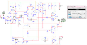
Just realised i uploaded the wrong schematic, there is an connection error around Q10/D5/R21. Will update the schematic !
Just realised i uploaded the wrong schematic, there is an connection error around Q10/D5/R21. Will update the schematic !
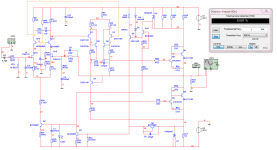
the complementary Elvee circlophone.
Waow! this circlophone is not "little and cheap" anymore: it is the "Posh Circlophone".
There are many worthwhile improvements possible over the basic topology.
The posh version includes one of the most useful: a FET input, that eliminates trade-offs between bias current modulation and input impedance.
The other modifications are quite sensible too.
I see one other point where easy improvements can be gained: replace R27 by a 2-wire current source (I have described some suitable varieties in other topics).
This will improve the PSRR, make R22 superfluous, and allow the same circuit to work from +/-10 to +/-100V without alteration.
Excellent work.
Hello Elvee,
I wonder that how this topology sensitive for faster output transistors (10~80 mhz). You pointed already that C12 should be 820pF for faster devices. Have you any suggesting indicator for sure that amplifier is healthy or not?
And bridged configuration.. has topology any drawback regarding to two amplifiers as bridged configuration? In this case, can we avoid source signal ground connected to each amplifier regarding to use of balanced signal?
Last edited:
printed PDF's, filled in the componentvalues. i really hope i didn't make mistakes. thank you for your patience
Hello powerflux,
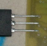
I etched and drilled one pcb yet. When I try to fit 2sc5200 (to-264) and some similar transistors (including mt-200) as output, but i saw that layout's leg distance was wider to fit. I checked original TIP3055's leg space dimensions in datasheet and I see that it is match to those I had to try. My measured two leg distance on pcb is about 7mm.TIP3055 in datasheet and other devices i tried are about 5.5mm.
Attachments
Last edited:
i used TOP3 package, since that's what i can get 2n3055's in except for TO3.
but i can change to TO-264 no problem. i prefer 2sc5200/2sa1943 myself.
pinning is the same tough.
if you've found other problems (such as packages, clearance etc. not another redesign), let me know and i will correct them. attached TO-264 version.
but i can change to TO-264 no problem. i prefer 2sc5200/2sa1943 myself.
pinning is the same tough.
if you've found other problems (such as packages, clearance etc. not another redesign), let me know and i will correct them. attached TO-264 version.
Attachments
Last edited:
i used TOP3 package, since that's what i can get 2n3055's in except for TO3.
but i can change to TO-264 no problem. i prefer 2sc5200/2sa1943 myself.
pinning is the same tough.
if you've found other problems (such as packages, clearance etc. not another redesign), let me know and i will correct them. attached TO-264 version.
Thank you for fast response and excellent pcb design of course. I will notice if I face any possible issue.
Last edited:
It has been tested with relatively fast transistors, such as the BDY58 (Ft=30MHz).Hello Elvee,
I wonder that how this topology sensitive for faster output transistors (10~80 mhz). You pointed already that C12 should be 820pF for faster devices.
C11 will probably become compulsory, but it is not a certitude: it will also depend on the driver and phase splitter transistors, and the wiring.
The wiring influence becomes more and more important when the Ft of OP transistors is increased
The first elementary test is to connect an oscilloscope to the output, and look for any HF parasitic signal.Have you any suggesting indicator for sure that amplifier is healthy or not??
This has to be done with a load, and with a low frequency sinusoidal signal of large amplitude (1KHz f.e.).
This is because parasitic oscillations can have multiple causes, and you need to sweep the whole current range for both halves of the PP to be certain not to miss something.
An oscillation could manifest itself by the thickening of the trace on the positive peaks of the waveform for example.
If you want to go deeper, you can inject a squarewave signal, and look at the transitions: you will be able to detect marginal stability issues, even if the amplifier is not oscillating: this will typically generate a prolonged ringing after each transition.
You have to be sure to feed a clean squarewave in the first place: if you use a relatively long, mismatched cable, this will create reflections that are almost undistinguishable from ringing.
I have given the schematic of a simple, cheap and clean squarewave generator here: http://www.diyaudio.com/forums/solid-state/189599-my-little-cheap-circlophone-9.html#post2637480
The bridged configuration has not been tested, but there is no reason it wouldn't work.And bridged configuration.. has topology any drawback regarding to two amplifiers as bridged configuration? In this case, can we avoid source signal ground connected to each amplifier regarding to use of balanced signal
You could feed a balanced signal that way, but be aware that any common-mode signal or offset will eat up output dynamic.
With a well balanced capacitively coupled signal, this should work perfectly.
@Elvee
When I asking, I was aware that your early posts regarding same issue. In fact, as an average diyer, I have no facility for measuring Mhz level signals. I think it is the best to ask for a favor from a oscilloscope owner from my around.
Thank you.
When I asking, I was aware that your early posts regarding same issue. In fact, as an average diyer, I have no facility for measuring Mhz level signals. I think it is the best to ask for a favor from a oscilloscope owner from my around.
Thank you.
An oscillation could manifest itself by the thickening of the trace on the positive peaks of the waveform for example.
Sorry for misunderstood. Does this mean, I can trap a HF oscillation even with analyzing a 1khz sinus or square waveform?
Yes and no: you need "something" to observe the trace, and the something must have a sufficient bandwidth, at least several MHz.Sorry for misunderstood. Does this mean, I can trap a HF oscillation even with analyzing a 1khz sinus or square waveform?
This rules out sound card based oscilloscopes for instance.
Reliably detecting an oscillation by other means would be difficult.
- Home
- Amplifiers
- Solid State
- ♫♪ My little cheap Circlophone© ♫♪