from the available winding area, i allow 80% for copper, 20% for insulation materials....
then from the 80% percent, i allot half of that for primary and the other half for the secondary.....
you choose your wire size this way....even if your formula tells you to use gage 14 say, if space permits, nothing stops you from using #13....
if you can not get the desired wire size fit into the window, then you use the next bigger core size.....
equations are fine, they are mere guides as to how to proceed with traffo buildup....design is iterative process....
bottomline, whatever figure that comes out of the formula does not mean you have to stick to it, it never happens that way in the real world.....
That is simply not true.
There are professional software programs providing you with a complete winding scheme (number of turns, gauges, interleaving thickness a.s.o) given a particular core size and voltage/current requirements, and these programs are accurate (transformers are physical things; you can calculate everything).
I have seen this in the "real world", just a pity that I can't afford something like that (the program I have seen "at work" is actually not for sale but is available on a lease basis).
The fact that we wind our transformers on an iterate basis has more to do with not having this software; the equations I use are perfectly accurate and actually the same as in these software programs. Doing the calculations by hand just takes more time; the outcome however is equally accurate.
3A/sqmm, not 3A/sqcm.Allowable currents to flow in the copper wire per area (cm²) symbol S
S = 3A to 5A per cm²
for 100VA transformer I use 0.25 to 0.3mm diameter cooper wire for primary (220volt)
0.3mm diameter and 5A/sqmm gives 353mAac
times 230Vac gives 81VA before accounting for efficiency. I'd guess at ~70 to 75VA for 0.3mm diameter and 5A/sqmm.
0.25mm diameter and 3A/sqmm gives 147mAac
times 230Vac gives 32.4VA. Reduce to ~25VA for output rating.
If my sums are correct then your primary wire looks too thin.
Can someone confirm where I have gone wrong?
Last edited:
Essentially right.
3A / mm² is for quality transformers, especially when temperature is a factor.
5A / mm² is for economy, where temperature, strayfields are not important.
Primary current is determined by secondary power (load), not by what the core might be able to deliver.
For example when I calculate a transformer which must supply 300 watts of secondary power, and I want B not exceeding 1T, I know a need a "600" watts core because of the larger required winding space. Wire diameter of the primary however can be calculated for 300 watts (no problem with the momentary higher inrush current at start up).
That is simply not true.
There are professional software programs providing you with a complete winding scheme (number of turns, gauges, interleaving thickness a.s.o) given a particular core size and voltage/current requirements, and these programs are accurate (transformers are physical things; you can calculate everything).
I have seen this in the "real world", just a pity that I can't afford something like that (the program I have seen "at work" is actually not for sale but is available on a lease basis).
The fact that we wind our transformers on an iterate basis has more to do with not having this software; the equations I use are perfectly accurate and actually the same as in these software programs. Doing the calculations by hand just takes more time; the outcome however is equally accurate.
if i live in your part of the world, then our "real" worlds would have been similar.......
unfortunately, materials available to you is not available to me vis-a-vis cores, you know your core manufacturers, i do not.... you deal with fresh virgin materials, i use scrapped traffos and cores....
i build traffos that work, are not too hot to touch and doesn't burn out in use, i must be doing things right.....
I understand Tony, of course.
But be it your or my world, the same formulas apply.
Important to know is what core material we deal with; the difference between 0.35 and 0.5 mm is physically obvious. When the laminations show an oxyde coating you can be pretty sure that the material is heat annealed.
So we have already 4 possibilities, covering almost all options.
For these options the important data are easily to find on the www, also for you.
I would not rely on RDH3, 4 or whatever; mostly out of date.
Good luck with your projects.
I know I am late for this discussion, but here are the formulas I used back in high school, when quality ready-made toroids were not available. I did design a number of hand made transformers with these formulas, and all worked reliably. These formulas are (1) oversimplified, (2) very conservative, made for poor quality iron, and (3) designed for 50Hz.
Power(W) = (Core-Area)^2; Core-Area is in cm^2
Turns-per-volt = (50..70) / (Core-Area); Core-Area is in cm^2
Primary turns = Primary voltage * Turns-per-volt
Secondary turns = Secondary voltage * Turns-per-volt * 1.2
Wire diameter = 0.7 * sqrt(Current), Current is in Amps
Looks like these are is agreement with the (complicated) formulas above.
Yes its should be mm²3A/sqmm, not 3A/sqcm.

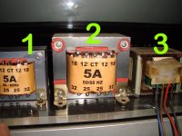
but I gonna confused with this image from my real world
no 1 = must be fake, 5A * 64v = 320VA to small for that power
dimension 3" * 2.5" * 1.75" (stack)
primary wire = 0.25mm diameter
secondary wire = 0.7mm diameter
no 2 = maybe its okay, 5A * 64v = 320VA, or maybe 5 * 32 = 160VA?
dimension 3.75" * 3.25" * 2.15"
primary wire = 0.5mm diameter
secondary wire = 1.2mm diameter
no 3 = was used in 30watt amp so its maybe quite good transformer, even the iron core is black in color, anyone know what is this core name?
all trafo for 220 volt ac input
the AWG table make me more confuse, from the shop that I bought wire they ask me in mm diameter not AWG's.
Can anyone show me the right AWG to metric conversion.
then for 0.25mm 0.5mm or 0.7mm diameter how much currents can flow safely?
Please tell me the actual reliable VA for no 1 & 2 ?
so my mind can be clear
I'm also read this
http://www.diyaudio.com/forums/power-supplies/191730-my-latest-traffo-build.html
very good traffo making, but tube is out of my range
Sir Tony, that winding machine is a DIY tool?
so cool 😎
Thanks
Attachments
Last edited:
Can anyone show me the right AWG to metric conversion.
Thanks
Google is your friend 🙂
ok, but sometimes I miss the right choiceGoogle is your friend 🙂
too much result
Maybe some experience of winding from you?
I already made some rewinding of trafo EI & toroids too.
some customize too but not sure about it work
not sure the ratting itself
So please give me your secret formula? 🙂
Last edited:
swgs awgs inches, millimetres, drill numbers, drill letters.
I used to have the five column table hung on the wall behind my lathe.
this one shows swg awg mm
Imperial Standard Wire Gauge to American Wire Gauge Comparison Table
I used to have the five column table hung on the wall behind my lathe.
this one shows swg awg mm
Imperial Standard Wire Gauge to American Wire Gauge Comparison Table
that winding machine is a DIY tool?
so cool
yes, i made wooden mandrels to help me in making coils....
please give me your secret formula?
there is no secret formula, trust me.......it is just plain hard work, but i enjoy it....
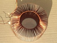
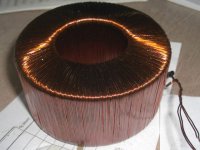
What about this toroid?
I hope this one is more interesting to discuss 🙂
but I still waiting someone to tell me the approximate VA for no 1 & 2?
Anyone can give me new formula for this trafo, please?
few years ago I made it,
it's okay or bad trafo
even the formula to make this trafo, I don't know
Maybe better if any suggestion to testing to know it is good or not
I don't have an AC A-meter
Attachments
Last edited:
Great thread !
I don't recall this being answered, but how is the equation A = sqrt(W) / K derived ? This has been the one design parameter about transformers that has always eluded me; how does the VA rating correspond to core size.
I don't recall this being answered, but how is the equation A = sqrt(W) / K derived ? This has been the one design parameter about transformers that has always eluded me; how does the VA rating correspond to core size.
I still waiting someone to tell me the approximate VA for no 1 & 2?
and i am waiting for you to give the core dimensions, core area is you can please....hard to tell from the photos....
i do not give credence to any label on the traffo alone.......
The gross over simplification of A= sqrt(w)/k is simply that: a rough fit for small transformers. Although, interestingly enough, watts = core area in (cm^2)^2 works out for a 50 kva pad mount transformer, a bit on the conservative side though, predicting 40kva.
Last edited:
how does the VA rating correspond to core size
IMHO, temperature rise is one single biggest factor......
for the same size of core, you might spec it at say, 100watts at 50*C temp rise, while another might spec it at 50watts 20*C temp rise....
i always go back to this site for refreshers, powertranschokes
It is, and the reason is that volume follows the cube, surface area the square. You have to reduce the power loss, or reduce the current density. At some point, you simply can't make a transformer any bigger, iron loss alone would melt the core. I believe they top out at about 1 KVA per kilogram for near gigawatt capacity.. A 50 kva pad mount transformer is typically 360 VA per kilogram, and 98.5+% efficient. A 1 kva transformer might be 200 va/kilogram, and only 95% efficient, even if you used the same iron.IMHO, temperature rise is one single biggest factor
IMHO, temperature rise is one single biggest factor......
A low B transformer will stay cool, but also stray fields will be minimal (two coil c-core transformers have already an advantage over EI), and the transformer will be more quiet; all these factors are somehow interrelated.
- Status
- Not open for further replies.
- Home
- Amplifiers
- Power Supplies
- Iron Core Transformer Formula