I built an amplifier with type 845 outputs (B+ 1170VDC) with bi-metal time delay "relay"s to give 15 second heater and filament warmup to half voltage, then full heater and filament voltage, then after 45 seconds total, B+ is switched by snap relay in primary with hysterisis for the delay "relay" heater. Current through the heater and filament transformers' primaries seemed low enough to let them just pass through that delay's contacts directly, although some tiny arcing is inevitable (and I've got lots of 'em to use up).
B+ is made by choke input FW bridge to a bunch of (used) 660VAC motor run capacitors. Well, you can guess what happened after a few years. I powered up one day and the heater and filament relay's contacts finally failed. B+ arrived on time and soared to upwards of two Kilojolts. Everything survived but Yikes.
I'm more careful to eyeball those contacts since then.
Thanks,
Chris
the instant that +B hits those fully heated cathodes, they are going to be passing a huge surge as the cathode by-pass caps charge up to establish the 'auto'/self bias point....
SNIP
I'm definately in the 'Non Delay' camp...😀
OK, so I get the non-delay rationale, except for the B+ hitting fully heated cathodes. As I understand tubes, B+ doesn't ever hit a cathode. It hits the anode and thereby draws current from the cathode. Now I can see how the arrival of full B+ could result in instantaneous draw from the cathode which then would run hot until the cap charges. But what about non-bypassed cathode resistors, or other cathode biasing schemes?
Please keep in mind I'm still trying to learn here.
Thanks,
Carl
You will still get a big positive pulse on the grid as the coupling capacitors charge, so you will still get a big (albeit lessened) anode current pulse even with fixed bias. Not that that really matters- valves have more than enough reserve to handle large current surges from cold.Now I can see how the arrival of full B+ could result in instantaneous draw from the cathode which then would run hot until the cap charges. But what about non-bypassed cathode resistors, or other cathode biasing schemes?
Delaying the HT does nothing except protect PSU smoothing caps from going over voltage. It certainly doesn't extend valve life.
Hi Chris
With choke input supplies it is a good practice to have a bleeder circuit in the PSU which ensures that critical current is drawn even if for some reason the amp itself does not draw enough current. This not only avoids voltage rise in such a case but also stabilizes the voltage a bit.
In a 845 amp such a bleeder will dissipate a lot of power. Even a higher value resistor which will not draw critical current will help to avoid that the voltage dioes not rise too much.
best regards
Thomas
B+ is made by choke input FW bridge to a bunch of (used) 660VAC motor run capacitors. Well, you can guess what happened after a few years.
With choke input supplies it is a good practice to have a bleeder circuit in the PSU which ensures that critical current is drawn even if for some reason the amp itself does not draw enough current. This not only avoids voltage rise in such a case but also stabilizes the voltage a bit.
In a 845 amp such a bleeder will dissipate a lot of power. Even a higher value resistor which will not draw critical current will help to avoid that the voltage dioes not rise too much.
best regards
Thomas
Hi Chris
With choke input supplies it is a good practice to have a bleeder circuit in the PSU which ensures that critical current is drawn even if for some reason the amp itself does not draw enough current. This not only avoids voltage rise in such a case but also stabilizes the voltage a bit.
In a 845 amp such a bleeder will dissipate a lot of power. Even a higher value resistor which will not draw critical current will help to avoid that the voltage dioes not rise too much.
All good points. I should have interlocked the B+ delay "relay" to heat *after* the heater and filament delay - can't remember anymore why I didn't. The biggest (literally) mistake I made in that amplifier was to put both channels and the power supply all together on one (big) chassis. Seemed like a good idea at the time, but I was younger and stronger in 1994. Today I can almost, but not quite, pick it up off the floor. It's about 120 pounds - bad thinkin' there.
Thanks,
Chris
So here's another related question. I like to swap speakers while building and testing different combinations with my amps. I may stop using the B+ switch for delaying the HT to the plates, but could that switch be used to protect the amp and OPTs while switching speakers? I don't want to leave the outputs unloaded, at least while the B+ is on. But fully powering down to switch speakers seems like overkill and takes a little longer - and the longer the interval between listening sessions the less I am able to discern small differences in sound.
So the question is, will the amp be protected from the unloaded outputs if I leave heaters on but power down the B+? And, more importantly, is that a good thing to do?
So the question is, will the amp be protected from the unloaded outputs if I leave heaters on but power down the B+? And, more importantly, is that a good thing to do?
You would need to do everything in the right order, as you must not switch B+ with no speaker connected. Looks risky to me. Easier on the amp and speakers to switch off properly.
So here's another related question. I like to swap speakers while building and testing different combinations with my amps. I may stop using the B+ switch for delaying the HT to the plates, but could that switch be used to protect the amp and OPTs while switching speakers?
Turning off the B+ is not enough. You have to wait until the bleeder resistors draw down the voltage in the filter caps. There is still hot B+ inside the amp for some number of seconds after the switch is opened. So if you were carful and knew how long to wait it could work.
But better plan is to buy a "make before break" type switch that can swap speakers without ever causing a disconnect. Then you can flip back and forth instantly.
The best protection you can install is simply to wire a (roughly) 270 ohm power resistor across the speaker jack. Then even if the speaker is un-plugged there is still a load on the transformer. Yes 270R is not the same as an 8R speaker but 270R is much smaller than infinity. It is about enough to prevent an OPT failure. But 270R is high enough that when parallel with an 8R speaker the speaker's impedance dominates the calculation.
You might even try using a switching jack for the speaker output and switching in a low value resistor. But (1) switching causes transients. The 270R resistor is always there and works even if the disconnect is from the speaker end of the cable. and (2) a low value resistor must be rated for double the amp's full watage. I've never bothered with switching speaker jacks
Turn the master volume to zero is all that is really needed.
Belts and braces would then add loading - such as full time 270 ohm - or make a speaker extender cable, with a shorting switch in, for when you swap speakers. And/or add a MOV-R protector across the OT primary windings to snub any over-voltages that are the root cause of your concern (ie. damaging the OT).
Belts and braces would then add loading - such as full time 270 ohm - or make a speaker extender cable, with a shorting switch in, for when you swap speakers. And/or add a MOV-R protector across the OT primary windings to snub any over-voltages that are the root cause of your concern (ie. damaging the OT).
Turn the master volume to zero is all that is really needed.
Belts and braces would then add loading - such as full time 270 ohm - or make a speaker extender cable, with a shorting switch in, for when you swap speakers....
One thing you are protecting from is when you are playing loud with the master volume on "11" and then the speaker blows and unloads the transformer. Those 5W sandstone resistors only cost me 45 cents and they fit perfectly between the legs of a plastic Cliff jack.
The consideration of whether to switch B+ is much more complicated than some would like to believe.
The answer depends on your design goals.
Firstly, we have to identify the mechanisms.
1. The cathode stripping effect found in Transmitting valves, operating at high (1kV+) voltages is well-known, and should be accounted for in kV-level designs. This is a kind of brute-force ripping of cathode particles from the emissive surface, before the heater can start the proper thermionic action. With receiving tubes, operating at much less than 1kV, cathode stripping has not been confirmed, so far as I know.
2. However, there remain multiple instances where professional equipment designers are explicitly instructed to preheat the valve before applying the anode voltage.
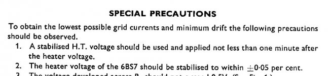
Start with Electrometer valves. The attached picture is a grab from the STC 6BS7 data sheet. This is a low-noise audio pentode, which serves as a fine upgrade for the EF86. Its high quality allows it to be used for electrometer duty - where ultra low grid currents are required. Now why could electrometer duty possibly require a 1-minute (minimum) preheat before applying anode voltage? We will see.
.
The answer depends on your design goals.
Firstly, we have to identify the mechanisms.
1. The cathode stripping effect found in Transmitting valves, operating at high (1kV+) voltages is well-known, and should be accounted for in kV-level designs. This is a kind of brute-force ripping of cathode particles from the emissive surface, before the heater can start the proper thermionic action. With receiving tubes, operating at much less than 1kV, cathode stripping has not been confirmed, so far as I know.
2. However, there remain multiple instances where professional equipment designers are explicitly instructed to preheat the valve before applying the anode voltage.
Start with Electrometer valves. The attached picture is a grab from the STC 6BS7 data sheet. This is a low-noise audio pentode, which serves as a fine upgrade for the EF86. Its high quality allows it to be used for electrometer duty - where ultra low grid currents are required. Now why could electrometer duty possibly require a 1-minute (minimum) preheat before applying anode voltage? We will see.
.
Attachments
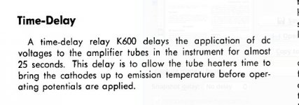
Next up, professional instrumentation. It doesn't get more professional than Tektronix, so let's look at the 551 tube-based oscilloscope. The snip is from the 551 manual, where you can see explicitly stated that B+ is delayed, to allow that tubes to warm up before anode voltage is applied. Given that the 551 is designed for accurate MEASUREMENT, avoidance of excess grid currents are the first consideration for the TEK amplifiers.
Attachments
The explanation.
The most credible explanantion for problems with excess grid currents, caused by cold application of anode voltage was
published by J.H. van de Weijer, a cathode designer at N.V. Philips CRT division in Eindhoven. I have been told by Frank
(fdegrove here on DIYA) that this text first appeared in the Dutch Audio Magazine "Geluid en Techniek" in the 1990s, when van
de Weijer retired.
Although he refers to cathode-stripping, please remember that this is not the same as Transmitter (brute-force) cathode
stripping. Here is the full note :
One may assume that a thermionic valve's susceptibility to the stripping
phenomenon primarily depends on its cathode's design, and indeed that the
side effects caused by this are most prone to be seen in high grid
impedance low level signal tube circuits and their aging behavior:
Indirectly heated (generally Nickel) cathodes coated with a rare earth
metal oxide electron emission "cement" compound are prone to mechanical
stress caused by thermal cycling; i.e.: the heating and cooling of the
cathode. (Manufacture dependent).
The ceramic nature of the indirectly heated cathode's emissive coating
with its (from the metal cathode carrier) differing thermal expansion
coefficient may cause surface material to crack and become "loose". The
thus gradually "powdered" ceramic cathode emission surface may keep
minute amounts of electrical charge stored after cooling down; the
surface in cold state remains nonconductive. Minute amounts of these
cathode borne particles, either with remaining charge or electrically
polarized upon sudden apply of anode voltage, may "dust off" and clog
onto the most nearby "sieve" i.e.: the control grid; cathode stripping
has happened, and here it is that this less heard of tube
degradation/aging mechanism (not discussing others) occurs!
Consider this:
The grid clogged particles due to radiant heating from the nearby cathode
will start to behave as pointwise cathodes themselves, causing beyond
normal grid current, this has the effects of:
-Drift in those high impedance biased control grid circuits: And this
just in the unwanted direction: Take a tube endstage which is
capacitive coupled from the phase inverter and DC biased through (say)
50 kOhms: Current runs from the anode into the control grid and
therefore shifts the grid bias voltage to a less negative value...
There you go...
(Ever wondered why some tube manufacturers specify a maximum grid bias
resistance?)
-Causing excess noise.
-Etcetera, you don't want to know.
Now, how to be most gentle to your indirectly heated tubes and give them
a long life: (and this also applies for all fellow guitar players having
a "stand by" switch at hand):
SWITCH ON:
Switch on from standby mode: i.e. only fire the filaments, wait somewhat
longer than fully "glown" up, then switch from standby to power (B+).
(i.e.: B+ may be suddenly switched on, but only after full filament
warm-up) (with regards to "cathode stripping": The cathode is now
conductive: All localized cathode charge will have drained).
SWITCH OFF:
The same sequence reversed: I.e.: Turn off B+, wait, and only then turn
off the filament supply; This will gradually and properly discharge all
charges.
With regards to cathode Stripping; this will assure no charge will
remain stored locally on the susceptible cathode surface and so forth...
Copyright 1996 J.H. van de Weijer
This article may be freely distributed,
stored, copied and printed for non-
commercial use, provided the integral
text including this notice is kept
unmodified.
I wanted some independent verification of this, before republishing it. After a lot a looking around, I found that there are still some firms engaged in cathode and Electon Tube design, so I wrote to the one that looked most Engineering-Friendly - namely Bernie Vancil of ebeam:
Bernard Vancil e-Beam Inc.
Interestingly, Bernie has a history of designing cathodes for Tektronix.
I sent him a copy of the van de Weijer text to see whether he thought it to be real, and happily got a response today:
For amplifier design, the van de Weijer effect (I don't say "cathode stripping" to avoid confusing the two completely differing mechanisms) may or may not worry you.
- It will NOT degrade your tubes emission, nor cause them to blow up.
- in many circuits, you might not notice it at all.
- if you use a particular tube for a short time, then change it to a different one, the effect may not take hold.
However, circuits which show a high impedance at the grid, or are at risk from increased grid current, may well be degraded (over a long interval).
We also know that modern production valves are strictly built to a price, and are doubly unlikely to attend to the precaution specified by Bernie Vancil [operating the cathode at 1000 degrees C for 15-20 minutes]. I would suggest that if you are designing with new tubes, and have any high impedance grid circuits, you should take this warning seriously.
The other consideration is noise. Having emissive sites on your grids is NOT helpful if you are expecting low noise. And emission from the grids will give distortion, too.
It's your design, so you must decide, based on what you think. And, it's your money, and if you have spent it on some expensive NOS, you might give a thought to how to make it last for the longest time.
My personal solution uses damper diodes - 6CJ3 (or PY500 etc etc). These give a delay AND a very slow rise time to the B+, so that there are no surge currents. I also use a separate switch for the filaments and heaters, so that I can leave these heating for a minute after switching B+ OFF. I do this while putting the LP back in its sleeve!
Damper diodes can be used in Fullwave or hybrid bridge and sound excellent in both configurations, provided you implement them properly. Or you can use SS rectifiers with a damper in the dc line (PY800 etc, very cheap).
Bernard Vancil e-Beam Inc.
Interestingly, Bernie has a history of designing cathodes for Tektronix.
I sent him a copy of the van de Weijer text to see whether he thought it to be real, and happily got a response today:
**********************************************8Dear Mr. Coleman,
I have not seen this phenomenon, but believe it could occur. If the
cathode coating is properly broken down and activated, the particles of
barium, calcium and strontium oxide will be sintered together. This is
done by operating the cathode at 1000 degrees C for 15-20 minutes. This
would probably eliminate the problem. However, I doubt that receiving
tube manufacturers would go to this much effort.
Regards,
Bernie Vancil
President, e beam, inc.
Vacuum Electron Devices - eBeam, Inc.
For amplifier design, the van de Weijer effect (I don't say "cathode stripping" to avoid confusing the two completely differing mechanisms) may or may not worry you.
- It will NOT degrade your tubes emission, nor cause them to blow up.
- in many circuits, you might not notice it at all.
- if you use a particular tube for a short time, then change it to a different one, the effect may not take hold.
However, circuits which show a high impedance at the grid, or are at risk from increased grid current, may well be degraded (over a long interval).
We also know that modern production valves are strictly built to a price, and are doubly unlikely to attend to the precaution specified by Bernie Vancil [operating the cathode at 1000 degrees C for 15-20 minutes]. I would suggest that if you are designing with new tubes, and have any high impedance grid circuits, you should take this warning seriously.
The other consideration is noise. Having emissive sites on your grids is NOT helpful if you are expecting low noise. And emission from the grids will give distortion, too.
It's your design, so you must decide, based on what you think. And, it's your money, and if you have spent it on some expensive NOS, you might give a thought to how to make it last for the longest time.
My personal solution uses damper diodes - 6CJ3 (or PY500 etc etc). These give a delay AND a very slow rise time to the B+, so that there are no surge currents. I also use a separate switch for the filaments and heaters, so that I can leave these heating for a minute after switching B+ OFF. I do this while putting the LP back in its sleeve!
Damper diodes can be used in Fullwave or hybrid bridge and sound excellent in both configurations, provided you implement them properly. Or you can use SS rectifiers with a damper in the dc line (PY800 etc, very cheap).
I've seen a few reports of failure mechanisms due to the initial surge stress on heater energisation, such as Gano & Sandy 1958. It would seem to me from Rod's information that this stress mechanism would likely be the dominant contributor to the effect described by van de Weijer.
Turn-ON current surge may well hamper reliability. I once used JJ EL84s on ac heat, and disliked the creaking noise it made when applying a high-power 6.3V ac supply - it sounded like mechanical distortion of the heater, due to the surge current (which can be 10x the operating current).
Do you have a pointer to the article?
Personally, I use constant current supplies for (signal) indirect AND directly heated tubes.
Using raw dc or voltage regulators for DHTs is hazardous enough. A cold 300B might draw 5.5A at turn-ON, and some Transmitting triodes show almost zero (<0.1) ohms when cold, and will draw whatever the supply can deliver!
DIYers who have experience of the Svetlana, AVVT and EML DHTs will vouch that filament breakage at at turn-ON is a serious failure mode for DHTs. My CCS kits for DHT heating avoid this high turn-ON current, as well as giving much better sound with any DHT.
One overlooked degredation phenomenon of applying B+ before the cathodes are up to temp is positive ion bombardment. All tubes contain some gas, and this gas becomes ionized when electrons flow between the cathode and plate. When gas is ionized, one or more electrons are stripped from the atom, which gives it a positive charge. This positive ion is attracted by, and accelerates towards, the cathode.
Now, an ionized nucleus is vastly heavier than an electron, so it doesn't achieve near the speed. OTOH, being massive, it still packs a wallop. When a tube is in normal operation the space charge (a cloud of electrons) around the cathode acts as a shield of sorts. The action around the cathode with respect to ions is somewhat complicated, but suffice it to say that it essentially prevents the cathode from being bombarded by the ionized nuclei in the tube. This is why mercury vapor rectifiers don't get their oxide cathodes blown off by the massive amounts of ionized mercury atoms that the tube relies on for its function. Anyone who has ever read data on a merc rectifier knows that there are explicit warnings NOT to apply HV to the tube before the cathode is fully up to temperature. Doing so will very rapidly destroy the cathode due to positive ion bombardment.
As it turns out, the same thing can happen in a receiving tube, even at low voltages. As the cathode begins to heat up, it starts emitting electrons. However, if the plate (and/or screen) is positively charged, the few electrons emitted by the still relatively cool cathode will be immediately drawn away, and on their way to the plate they will inevitably ionize some gas in the tube. Since the cathode is not yet surrounded by a space charge, the ions will freely bombard the cathode. How much damage it does is determined mainly by the hardness of the vacuum in the tube, the voltage applied, and how long it takes the cathode to heat up enough to form a space charge. The damage is cumulative, so every time a power cycle is completed a little more life is taken.
As others have pointed out, tubes still lasted a long time in older equipment. I think part of that was due to the quality of the tubes and the design of the equipment. Engineers couldn't design equipment that only functioned if the tubes were at 95% or better. They had to allow for age and loss of emission, so they tended to run the tubes conservatively. This had two advantages: first, the tube could degrade much further before it needed to be replaced, and a conservatively run tube means it is running at lower current which not only makes it last longer in service, but the larger negative grid potential during warmup (as soon as current flows for a cathode biased tube) means lower current (and ionization) during cathode warm-up.
I don't claim to have all the answers, but I do believe delaying B+ until the cathode is fully warmed up is a very good idea. Others have mentioned that slamming tubes with HV can have other effects, such as temporarily overdriving outputs as the coupling caps charge. I see a few solutions: Use a slow warm up rectifier; use a method that applies the B+ slowly (i.e. a resistor that gets bypassed with a switch - choke input supplies help too); apply B+ to the preamp tubes before applying plate and screen voltage to the outputs. Lots of options when you think about it.
I think I have seen recommendations for applying heater only for many minutes for valves that have not been used for some time, with the intent being to allow the getter some time to lower the density of stray atoms/molecules that have built up over time.
If the valve is in normal frequent use then the benefit of initial heater warmup may be quite negligible, as it would rely on a time that allows the getter to raise its temperature, and a time to allow the density of stray atoms to significantly reduce (and the level of strays may be as low as they are going to get anyway).
Ciao, Tim
However, if the plate (and/or screen) is positively charged, the few electrons emitted by the still relatively cool cathode will be immediately drawn away, and on their way to the plate they will inevitably ionize some gas in the tube. Since the cathode is not yet surrounded by a space charge, the ions will freely bombard the cathode.
Wouldn't the space charge attract the positive ions, thereby bombarding the cathode? Or does the space charge provide a minute barrier, not letting the positive ions actually reach the cathodes? Just a theoretical interest here, and it's based on my image of positive ions and their inertia blasting through the electron cloud and hitting the cathode. Nothing empirical in my question.
So I have one more related question. Taking a nod from the Bottlehead Quickie, what if we kept B+ ALWAYS powered on, but used the filaments to switch on the amp? With no cathode emission, seems like there'd be no conductance and therefore no current flowing in the tube - the amp would be, to all purposes, off. Turn on the cathode and the amp is on. This would mean no sudden surge of B+, though it would be present the moment the filament started burning, so the ionization would presumably occur as before). This would, of course, not work with a direct coupled amp (need that cap coupling to keep the DC sitting idly at the anode), and maybe would be moot given the placement of the OPT?
I'm just sayin'
Last edited:
- Home
- Amplifiers
- Tubes / Valves
- To switch B+ or not?