half the rail voltage (40V DC) at Q1's drain.
The schematic of page 61 specify the work with the CCS , but it is 30 Volt rail voltage , not 40 or 60 . That version works and sounds (!) pretty good . I do not believe it will be scalable , for higher rail voltages , you'll need different values of R6 R10 and R7 .
🙂
Hi Steffano
This was actually using a 30-0-30 transformer that was meant for the Delite and I didn
This was actually using a 30-0-30 transformer that was meant for the Delite and I didn
Seems to have cut me off halfway...
Anyway, what I wanted to say was that I didn't want to get another custom wound transformer. Hence the 30-0, 30-0 (not 30-0-30) secondary windings. I used an 8 Ohm 50W at R5 instead and got pretty close but that would've defeated the purpose of the CCS. Pretty good sound though. I will take your advice of changing R6, R7 and R10. I would be grateful if you can tell me what voltages should be expecting at the IRFP240's gate? I am rather clueless at biasing unless it's a tube amp.
Thanks in advance.
30-0, 30-0 (not 30-0-30) secondary windings. I used an 8 Ohm 50W at R5 instead and got pretty close but that would've defeated the purpose of the CCS. I would be grateful if you can tell me what voltages should be expecting at the IRFP240's gate? I am rather clueless at biasing unless it's a tube amp.
Thanks in advance.
- with that secondaries it is possible to build 2 separate PS and have 40 volt or so each at Vdd ( and then go for dual mono power supply ) .
-As far as I understand it , from a previous Nelson's post , it is possible to raise the value of R5 , that it means to me ( if I 'm not wrong ) it can be set almost to zero ohm , but I didn't try it .
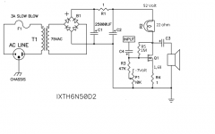
-The enanchement mode Mosfet IRFP240 , turns on typically at VGS= +3,5 Volt ( or little more ) .
In the example posted of CCS if Vdd is 30 volt , Voutput is half of it 15 volt , then R5 would have 1,6 volt across. The Gate of Q2 will be at : 15 + 1,6 + 3,5 = 20,1 volt in theory .
- Remember that the bias current is set by Q1, which is self biasing device , depending on R4 and its Vds .
PS : Later Will try to post another CCS based example with IRFP240 since i recall using for Q2 the IRFP 044 previously , and of course it has slightly different values settings for the bias .
Hi Steffano
Thank you for your reply. Yes, the amp is a dual mono design. I have used an 8 Ohm resistor at R5 but is this the way to do it?
Voltage at R4 is 1.8V = 1.8A@1 Ohm and I am getting all the voltages proper based on that current draw.
My questions are:
1. What is the purpose of R6, R7 and R10 and how do I use them effectively?
2. Am I supposed to get 20V DC (1/2 Vdd 40V DC) at Voutput which is at Q1's drain?
3. As mentioned above, can I change the value of R5?
Thanks again for your patience.
Hi Steffano
1. What is the purpose of R6, R7 and R10 and how do I use them effectively?
2. Am I supposed to get 20V DC (1/2 Vdd 40V DC) at Voutput which is at Q1's drain?
3. As mentioned above, can I change the value of R5?
1)The purpose of R6 , R7 R10 are to set 1/2 Vdd at the output , so yes for question 2)
3) yes
Hi Steffano,
Got it. Thanks.
Welcome .
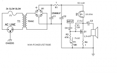
Below , in the attached schematic , I have another example of personal experiment , little feedback loop , negative voltages to set the working line .
During the listening I've found that carefully trimming p1 to obtain -Vgs = V on R4 the amp started to fly . While with differen values the sound is more boomy on the bass and less precise on the highs .
I wonder if this thing is effectively important or just the result of this particular implementation , considering also that my speakers are set up with a current source equalization .
(V at the drain of Q1 is 13,7 Volt.)
Thanks
Attachments
Last edited:
Stefanobilliani,
IS Q1 a R085, or the IXYS?
Also, is 1.68v over R4, or is that R?
I think your saying - measured vgs (measuring at gate and source) should be about the same voltage as measuring voltage across R4. (?)
Tea
IS Q1 a R085, or the IXYS?
Also, is 1.68v over R4, or is that R?
I think your saying - measured vgs (measuring at gate and source) should be about the same voltage as measuring voltage across R4. (?)
Tea
Stefanobilliani,
IS Q1 a R085, or the IXYS?
Also, is 1.68v over R4, or is that R?
I think your saying - measured vgs (measuring at gate and source) should be about the same voltage as measuring voltage across R4. (?)
Tea
Yes in this example it is IXYS . I did something similar with the R085 .
Yes for second question : 1,68 is the voltage across R4 .
so Vgs ( wich is negative ) is trimmed for the same voltage across R4 .
I don't imagine why , but the fine tuning gives instantly better sound .
The R085 is ... different thing , sound much better musically ( the bass much more articulated , the midrange sweet non agressive , highs good )but <maybe> a bit less easy to live with ... ( and here also don't know why ).
I might probably investigate better on the audio source , since I have very good computer software handy .
... and of course , the main difference could be the light bulb , and the loading lines . Infact I found in the IXYS case the light bulb to be equivalent to 22 ohm ; different in the R085, it goes to 15 ohm ...
Last edited:

Are the Gate and Source tied together with R4?
Have you managed to work it out?
No🙁. I need one of the brainy one's on here to tell me if the diagram is showing an external or internal connection between G & S😕
An externally hosted image should be here but it was not working when we last tested it.
No🙁. I need one of the brainy one's on here to tell me if the diagram is showing an external or internal connection between G & S😕
An externally hosted image should be here but it was not working when we last tested it.
I'm sure the main man will be only too happy to help 😉
schematic is soooooo simple
G&S are together on GND
I am VERY Simple!😕
Phew...! Well maybe after all this time, I can get it working 😀
Thanks Zen Mod😎
Instead of using that 300w light bulb you could use 4 6as7 tubes and fool eveyone
into thinking it was atube amp.
into thinking it was atube amp.
- Home
- Amplifiers
- Pass Labs
- Pass "DeLite" Amp from BAF