I'm dubious about whether a speaker has enough directivity to create a level shift adequate to offset the lateral poistion shift, let alone overcompensate for it. 2ms of shift means you moved about a 1ft left (1ms farther from 1 speaker, 1ms closer to the other), lets call it a ft and a half since were are moving away on an angle, and in this distance the polar patern of the units has to rise/fall
Exactly. I came to the same conclusion on the basis of other works that deal with the presedence effect.
To everybody, I like the way the discussion is developing - lot's of good input and a couple new contributors. keep it up!
I can't prove it scientifically, but I think a lot of depth perception (whether it's an auditory illusion or not) comes from low frequencies - 100-300Hz or thereabouts, and deep notches in this range can tend to "compress" the sense of depth of the sound field, regardless of whether they are caused by floor bounce, "back" (behind the speaker) wall bounce, or modal effects.
Eliminate those deep notches and I find the sense of depth improves. The amount of absorption you have behind your speakers would certainly improve the response in this region. (Have you measured the change with and without between 100-300Hz ?)
I agree. I've done a lot of work in this regard, and can really hear the difference in a setup where it is done right. A null in that region can make a speaker sound thin, but ironically, with other material, it can sound kind of too throaty. I suspect this is because of the contrast in volume between the null and the peaks surrounding it. Really screws up the imaging too.
This vocal range is extremely important.
This is a great goal, and I agree that when it is accomplished, the results are noticeably better. The thing is, the vocal band starts around 200Hz, and male voice even goes doen to 100Hz. So there are very few systems that can actually do this.
Building an absorber isn't🙂
Yes exactly.As you know, the issue is time intensity trading. Shift sideways and there is a time discrepency that shifts the image. Increase the level of the far source the right amount and the image will be pulled back to center.
Your analysis of the change in differential time delay with lateral movement is faulty.How much level for how much shift?
I'm looking at a Deutsche Welle document .
http://www9.dw-world.de/rtc/infotheque/sound_perception/sound_perception.pdf
See figure 7 (Everybody read this paper because it is a good overview of what we are talking about!!). It shows a very linear dependence with 2ms of shift being offset with 16 dB of level.
I'm dubious about whether a speaker has enough directivity to create a level shift adequate to offset the lateral poistion shift, let alone overcompensate for it. 2ms of shift means you moved about a 1ft left (1ms farther from 1 speaker, 1ms closer to the other), lets call it a ft and a half since were are moving away on an angle, and in this distance the polar patern of the units has to rise/fall over 16dB to overcompensate.
You've treated it as if the speakers are directly to the sides of the listener (180 degrees separation) along a straight line where a one foot left listener displacement would be 1ms closer to the left speaker and 1ms further from the right speaker.
This is not the case at the apex of a 60 degree stereo triangle. Moving 1 foot left laterally increases the distance to the right speaker considerably less than 1 foot, and the reduction in distance to the left speaker is even less again than the increase on the right. Simple trigonometry.
I don't have time to sit down and work out the exact numbers for the purposes of this post but suffice to say that with a normal 60 degree triangle 1 foot of lateral movement from the sweet spot is a time delay differential of far less than 2ms. (I may work out some numbers later unless someone else beats me to it)
Naturally it also changes with angular separation - the closer the speakers are together, the more lateral movement it takes to get the same time differential, thus the less amplitude change required to overcome the time delay and visa versa.
A wider separation does require a more directional speaker for this time/intensity trading to work well, (like the 45 degree point of a 90 degree CD design with a fairly tight pattern) but can provide a very wide sweet spot.
Juggling of the angular separation and toe in is required to find the optimum combination for a given pattern speaker for this sweet spot widening effect to work well.
One other observation I would make is that you don't need 100% trading of amplitude vs time delay to prevent the image collapsing completely to one side, that's only required to keep it perfectly in the centre. Having it just move to the side a little bit instead of complete collapse is still an improvement.
Last edited:
As you know, the issue is time intensity trading. How much level for how much shift?
I'm looking at a Deutsche Welle document .
I'm dubious about whether a speaker has enough directivity to create a level shift adequate to offset the lateral poistion shift, let alone overcompensate for it. 2ms of shift means you moved about a 1ft left (1ms farther from 1 speaker, 1ms closer to the other), lets call it a ft and a half since were are moving away on an angle, and in this distance the polar patern of the units has to rise/fall over 16dB to overcompensate.
Laser beam speakers.
David S.
This tradeoff is in Blauerts book as well. I don't remember the requirements being that extreme and in practice they certainly are not. I do this by design and it works quite well, although I can't say that its all time-intensity tradeoff, only that there really isn't a sweet spot in my system. The image is good and solid across the entire sofa. There really isn't even a noticable change across the sofa. So something works, I have always attributed it to this tradeoff.
I suspect that having a crossover in the upper midrange imaging sensitive area might cause anomalies in the systems ability to produce a stable phantom center image. The crossover electronics may be pretty consistent on both sides, but there's the lobing thing, and how it interacts with the room acoustics. For best imaging in the upper midrange, you want both speakers to deliver the exact same frequency response to the ear-brain mechanism. It would be interesting to see where everybodies crossover frequencies are (and the slope rates). I wouldn't be surprised to see that those who had a weak or tweeter based pinknoise had a crossover between 2kHZ and 6kHZ. Maybe low order as well. Mine are at 100HZ and 1.4kHZ (tri-amp'd, 4th order active).The problem is that we have 14 subjects on 10 different speakers. In the case of Radugazon, none of his subjects were able to hear a phantom image at high frequencies. There might something be wrong with the speaker or speaker/room setup, we don't know. On the other hand, me and my girlfriend were perfectly able to hear the high freq image at the center.
So for both cases the observations per speaker are consistent. If we then group by speaker instead of observer, N=10, 70% of the speakers is able put the high freq phantom image at the corerct location.
Okay guys, read what I said. The question was whether we can overdo time intensity trading. Simon, I factored up by 1.5 to cover the fact that shift was on the diagonal. Earl, I know you like directional speakers but a 16dB drop in the degrees equivalent to, let say 2ft shift to be generous? Not with the typical speaker unless you are falling into a null.
David S.
David S.
In the upper midrange, lateral imaging is mostly a function of amplitude comparisons (as opposed to timing comparisons). If your system has trouble creating a center image, then it follows that it would also be weak putting images anywhere else.uhm, I forgot - those pink noise tests - what are they for? can such pink noise panned in the center localization tests tell us anything meaningful about localization of virtual musical sources?
can anyone explain please?
The contribution of front wall energies (wall behind the speakers) is a function of time delay. Less than about 6mS is a bummer. Damping would definitely help. Longer than that gives you a "chorus" like effect, with a bit of comb filtering largely filled in by the large number of reflection paths, primarily on the Z axis, which can give a 3-D nature to any embeded reverbs, without trampling all over the lateral spaciousness and imaging.Difuse lateral reflections as long as they are > 10 ms. Shorter than that will cause problems with imaging.
I have found that the depth perception increases as the back wall (behind the speakers) has more absorption. You are suggesting the opposite. I'm not sure why that would be.
Earl, I know you like directional speakers but a 16dB drop in the degrees equivalent to, let say 2ft shift to be generous? Not with the typical speaker unless you are falling into a null.
David S.
I like "directional CD speakers", its not an either/or you have to have both. And I said that I wasn't sure that it was time-intensity tradeoff entirely, only that somethjing along these lines works. You can well imagine that I don't see how this can work if the speakers are not CD, but thats another discussion. And at any rate, your 16 dB number seems extreme. Maybe it is signal dependent, I don't know.
And remember its "level differential" (just as its time differential) left to right, one falls the other rises. In my case I can see this differential getting to the 6-8 dB point.
It's pointless debating this with rule of thumb numbers that seem greatly out of kilter, so I've done the numbers.Okay guys, read what I said. The question was whether we can overdo time intensity trading. Simon, I factored up by 1.5 to cover the fact that shift was on the diagonal. Earl, I know you like directional speakers but a 16dB drop in the degrees equivalent to, let say 2ft shift to be generous? Not with the typical speaker unless you are falling into a null.
I've made the following assumptions - a 60 degree triangle whose sides are each 2.5 metres, and a leftwards lateral movement of the listener of 30 cm (~1 foot - your original example) from the sweet spot.
I won't bore everyone with the calculations, but the results are a distance differential of 0.299 metres, which is a differential time delay of 0.87ms.
According to the chart in the reference you provided, this requires a 7dB amplitude shift to completely counteract, somewhat short of your suggested 16dB for 2ms.
We also have to consider the change in amplitude due to the difference in distance of the two drivers, with the left speaker becoming closer and the right speaker further away. From this effect alone the left speaker would be 0.49dB louder and the right 0.55dB quieter, so a total of 1.04dB of amplitude bias, which means we have ~8dB in total to make up for.
The next point to consider is that we aren't trying to make up 8dB with the polar pattern of one speaker but from two speakers, the left whose output is reducing by going further off axis, while the right is increasing by going further on axis, requiring an approximate contribution from each speaker of ~4dB.
The total angle change for the right speaker is 5.61 degrees towards being more on axis, with the left speaker going 6.32 degrees further off axis.
Is this enough for the required reduction depending on the speaker ? I'm not sure, but the theoretical position is not nearly as hopeless as first suggested.
Significantly, the left speaker which you are nearing is already starting well off axis and you are going further off axis, so you are potentially well down the slope of the off axis fall off - particularly if you're near the critical angle of a CD design, so it seems likely that more of the amplitude imbalance is made up from the reduction in the near speaker rather than the increase in the far speaker.
One unanswered question in my mind is whether amplitude trading must occur over the entire audio bandwidth, or whether it's enough to do so at "higher" frequencies only, say from the presence region up. My speakers only start to become directional at about 2Khz and above, and yet toeing in front of the listener still seems to work in widening the sweet spot.
Measurements I've made in the past seem to show that amplitude imbalances between left and right in the presence region have much more effect at offsetting the apparent image location to the side than the same level of imbalance in the ~1Khz region for example, speakers with matched response from 2-5Khz but 1dB down on one channel from 500-1500 can still image from the centre on most music, whilst a matched response from 500-1500 but 1dB down on one side from 2-5Khz skews the image to one side quite badly.
Whatever the exact mechanism is, it seems to work, and maybe there is more to it than simple time/amplitude trading. As I suggested before, 100% trading is probably not required to keep the stereo image from collapsing entirely, it's possible that even 50% trading will keep the phantom image "somewhere in the middle".
Last edited:
4Khz, 18dB/oct passive here, and I get good phantom imaging on the noise tests, so I'm not sure what that does to your theory 🙂I suspect that having a crossover in the upper midrange imaging sensitive area might cause anomalies in the systems ability to produce a stable phantom center image. The crossover electronics may be pretty consistent on both sides, but there's the lobing thing, and how it interacts with the room acoustics. For best imaging in the upper midrange, you want both speakers to deliver the exact same frequency response to the ear-brain mechanism. It would be interesting to see where everybodies crossover frequencies are (and the slope rates). I wouldn't be surprised to see that those who had a weak or tweeter based pinknoise had a crossover between 2kHZ and 6kHZ. Maybe low order as well. Mine are at 100HZ and 1.4kHZ (tri-amp'd, 4th order active).
It may be a good thing, from the point of view of imaging clarity, that you have the 3pole cutoff rates. It's when two physically displaced drivers put out the same thing at the same time, that you get lobing (which moves around with frequency). The tighter the crossover slopes, the less of the frequency range gets damaged in this way. I paid the big bucks for the Seas Millenium one inch domes largely so I could move my crossover point down to 1.4kHZ (out of the freqs that give us some of the most important imaging cues). Only a few tweeters that I know of can do that range elegantly both in frequency response and Xmax.4Khz, 18dB/oct passive here, and I get good phantom imaging on the noise tests, so I'm not sure what that does to your theory 🙂
Member
Joined 2003
It would be interesting to see where everybodies crossover frequencies are (and the slope rates). I wouldn't be surprised to see that those who had a weak or tweeter based pinknoise had a crossover between 2kHZ and 6kHZ. Maybe low order as well. Mine are at 100HZ and 1.4kHZ (tri-amp'd, 4th order active).
700Hz, 8th order active
I think all other things being equal a steeper crossover slope (up to a point) results in better imaging due to reduced lobing and off axis destructive interference, especially if you're using physically large drivers that force a wide centre to centre separation.It may be a good thing, from the point of view of imaging clarity, that you have the 3pole cutoff rates. It's when two physically displaced drivers put out the same thing at the same time, that you get lobing (which moves around with frequency). The tighter the crossover slopes, the less of the frequency range gets damaged in this way. I paid the big bucks for the Seas Millenium one inch domes largely so I could move my crossover point down to 1.4kHZ (out of the freqs that give us some of the most important imaging cues). Only a few tweeters that I know of can do that range elegantly both in frequency response and Xmax.
On the other hand, I try to avoid putting any crossovers in the "telephone range" of 300-3000Hz, to me having the entire midrange and a reasonable margin on either side of it produced by the same driver seems to be beneficial to imaging and coherency, again especially so if the design requires larger than typical driver spacing.
It's pointless debating this with rule of thumb numbers that seem greatly out of kilter, so I've done the numbers.
Your scenario sounds good and I accept your math but you are being a little misleading regarding where this started from and what I said. When I suggested that nulls where the cause of the contrary shift in stereo image you said that it was more likely an overcompensation of the time intensity tradeoff.
My mental math said that sound at about 1 foot per msec would take a 1 foot net distance shift for 2 msec. This is because the difference is double the lateral shift since you are getting closer to one unit and farther from the other. I realized there would be a vector slope factor so I upped the 1 ft to 1.5. Your math is more accurate. Sound travels a foot in .87 msec and the geometry of your 60 degree triangle cuts the shift by a factor of 2 (not the 1.5 I guessed). In the end the 1.5 feet (I did not say 1 foot) I mentioned would require a 13dB balancing shift, plus your 1 dB for drop due to distance. So we are at 14dB by proper calculation rather than 16 dB by my estimate!
Note that 14dB and the 1.5 ft lateral shift would be perfectly complimentary amounts. One would balance the other out and the image would not shift at all (in theory). Your contention was that we had overcompensated for the time intensity difference to the point where the image shift went in the wrong direction. How much level shift would that take? Would it take as much as twice the 16dB per 2 msec that maintains a stationary image? It would have to be significantly greater than 16 for 2 to cause the contralateral shift.
If your speakers fall off 7dB in 6 degrees then they will just balance out (not overcompensate). Thats a pretty steep slope. A speaker's polar might make it at some frequency. I wonder if it will be flat in response at that point in the polar curve?
David S.
All I can say for sure is with my broad(ish) dispersion speakers placed relatively near each other, the image moved with me on pink noise. I leaned left, it stayed right in front of me. It would be cool to keep it exactly center with good time and amplitude trading. Are any of you smart fellers able to calculate a distance, angle, and directivity for this to happen? Hopefully this hasn't been done and I was too stupid to see it.
Thanks,
Dan
Thanks,
Dan
In my practice, I would opt for 90 degrees from speech upwards as a practical limit, offering good driver integration in the vertical plane. Sort of like Tooles. Directionality in lowest octaves is only an expensive and hard to achieve way of combating room anomalies. Make the room right and there is no more problem.
This is a great goal, and I agree that when it is accomplished, the results are noticeably better. The thing is, the vocal band starts around 200Hz, and male voice even goes doen to 100Hz. So there are very few systems that can actually do this.
Building an absorber isn't🙂
Let me see if I understood you. What I think you're saying is you prefer 90° directivity from the vocal region upward, and that below that, it is best to deal with room problems (modes) separately. I think part of why you prefer 90° directivity is it limits reflections from walls, and that where directivity cannot be maintained, absorbers can be used instead. Is that what you're saying?
If so, I agree with you about most of that, but differ with you on one small point. I agree that 90° is the most useful pattern for home hifi. I agree that it is best if it can be maintained down through the vocal range. And I agree that below that, room modes should be dealt with separately, with dense interference, using multiple subs.
The part I am not sure I agree with is the use of absorbers to deal with vocal range reflections. I mean, I agree that would be good if it were easily done. But my experience has been that absorbing sound in this range is really pretty hard to do. The absorber just has to be so thick, or at least spaced far from the boundary.
It's easy to absorb sound at the higher end of the vocal range, in the overtone region. But at the low end, around 100Hz to 200Hz, where the fundamentals of voices and many instruments like piano, guitar, cello, viola and trombone, these all fall into a range that's pretty hard to deal with. It's really pretty difficult to get an absorber to work in this frequency range. And since most speakers are spaced a few feet from walls, floor and ceiling, the sound from reflections in this frequency range happen to be the most mangled.
Anechoic chambers are only reflection-free down to a few hundred Hertz precisely because of this fact. It is pretty easy to absorb high frequencies but harder at low frequencies. You can use foam wedges, egg crates, even pillows, rugs or curtains to absorb high frequencies but low frequencies are harder, best damped with large membranes. A panel absorber can be made like a false wall.
At any rate, I want to reiterate that the constant directivity cornerhorn approach solves a lot of these problems directly. It isn't too hard to get the sound source acoustically close to the corner all the way up through the vocal range. This side-steps the problems of reflections off the adjacent walls. They become a baffle, a waveguide, a launch point.
No other loudspeaker configuration I know of does this. Not dipoles, not traditional horn/waveguide loudspeakers, nothing. They all radiate plenty of energy at the walls, making unwanted reflections. We can talk about what reflections are worse than others, but if you have the right corners, it seems pretty reasonable to me to take advantage of constant directivity cornerhorns. Then you don't have any reflections from the near walls to deal with.
Of course, if the tweeter is not acoustically close, then reflections from the near walls can still happen at high frequencies. But at high frequencies, it's almost trivial to solve. That's where wedge absorbers work great. Heck, at those frequencies, a pleated curtain will do the trick. But down at vocal range, you'd need a mound several feet thick to absorb the reflections. That's why the concept of the constant directivity cornerhorn is so appealing to me.
After one more session of intensive testing, it's for me impossible to found the magic position where two HF sources sound as one.
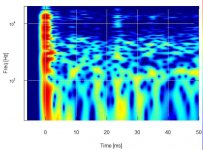
I did some polars, neat dipole pattern for the 4", but a naughty peak around 13 KHz and 45° incidence for the whole speaker. Definitively bad, but I wonder if it's relevant for the test as with a 48 dB lowpass 10000 Hz the results are the same.
Other suspected responsible, the reflections, contra or homolateral : look at the (wavelet) CSD joined taken at 2m50, the direct sound dominates largely, my room being wide (hehe, bigger than the Kiron !).
I give up to find an explanation.
Attachments
Hi, Wayne!
The metodology of obtaining absorption was not in question, it can be done using different techniques, including ones that you described. It can be built-in and concealed for a dedicated listening room, even within a living room. You don't need to go into anechoic wedge territory, there are cheaper, smaller and more elegant solutions. Of course, you also don't need the absolute perfection in that range, it's not practical or cost effective (even noticeable). If seeking perfection, stereo is the wrong format for you.
The price of multiple subs is equivalent to low freq absorbers, still I think that absorbers are cheaper. *There is another thing, when you put energy in a system, it has to go somewhere. Multiple subs didn't solve that. Just aggravated phase integration with mains. Multiple subs are the best solution if you don't have the place for absorption. You could also try careful main/sub setup if listening solo and then some EQ, but then see*.
Corner is natural extension of low freq horn. You get maximum efficiency & maximum modal excitation. Back to*.
Hope this helped clarify my comment.
- Status
- Not open for further replies.
- Home
- Loudspeakers
- Multi-Way
- What is the ideal directivity pattern for stereo speakers?