These are the maximum dimensions for the heatsinks in 1 monoblock:
Length: 150 mm
Width: 300 mm
Height: 80 mm
Regards,
Rudy
Length: 150 mm
Width: 300 mm
Height: 80 mm
Regards,
Rudy
Video already explained how to calculate..so...you will know
using the simple method...it works for my hot environment...may be good for your place during summertime.... and will be an overkill during the winter....average temperature here is 29 degrées celsius.... during winter drop to 22-24 degrées celsius.
regards,
Carlos
using the simple method...it works for my hot environment...may be good for your place during summertime.... and will be an overkill during the winter....average temperature here is 29 degrées celsius.... during winter drop to 22-24 degrées celsius.
regards,
Carlos
I have found, from the other forum mainly, some guys
that are not "that skilled"... they where evaluated by the questions they have made.... then i realise i should explain details to help them to assemble.
Here you have the first video.... i do think we gonna have two or three in total.
1 - Tips and tricks about MKIII Hx components - YouTube
From time to time you may hear strange things in my videos...this is because i am human and sometimes i do mistakes (half of the time will be better to say)
regards,
Carlos
simple and small question: the velleman 4700 speaker protection circuit, is that "strong enough" for this amp? since it can churn out almost 500W per channel (in some cases 🙂)... and if not,do i just replace the relays with more heavy duty ones? or is there another solution?
I do not know...send me the schematic
sometimes only the relay...sometimes other modifications are needed.
regards,
Carlos
sometimes only the relay...sometimes other modifications are needed.
regards,
Carlos
The circuit is good but you will almost certainly need to replace the relays. For 500W i'd say look at 30A car relays - anything else will probably just weld themselves closed.
Tips and tricks for MKIII Hx
Part II:
2 - Tips and tricks about MKIII Hx components - YouTube
regards,
Carlos
Part II:
2 - Tips and tricks about MKIII Hx components - YouTube
regards,
Carlos
Prepare yourself to face strong emotions
Do you know how to dance?.....you will dance even if you do not know.
MKIII Hx - Strong emotions to come - YouTube
regards,
Carlos
Do you know how to dance?.....you will dance even if you do not know.
MKIII Hx - Strong emotions to come - YouTube
regards,
Carlos
Heatsinks for MJE15033 & MJE15030
Greetings,
Does anyone know of a heatsink which matches the profile Alex drew for MJE15033 & MJE15033. I've been looking at heatsinks for TO-220 cases and I can only find the stamped, "wrap-around" style which fit on the board. The nice extruded ones are all too wide.
-Byron
Greetings,
Does anyone know of a heatsink which matches the profile Alex drew for MJE15033 & MJE15033. I've been looking at heatsinks for TO-220 cases and I can only find the stamped, "wrap-around" style which fit on the board. The nice extruded ones are all too wide.
-Byron
i'd be interested to hear what everyone is using for transformers . especially those in the usa .
i usually buy mine from antek .
cheers Woody
i usually buy mine from antek .
cheers Woody
i'd be interested to hear what everyone is using for transformers . especially those in the usa .
i usually buy mine from antek .
cheers Woody
I was going to give antek a try also, was not able to find any bad on them ...
i'd be interested to hear what everyone is using for transformers . especially those in the usa .
i usually buy mine from antek .
cheers Woody
glad someone is asking this question, also heat sink in USA.
How to measure your output power without damage your speakers
Full power connected to a speaker may blow it...so..use dummy load..video explains how to make it using cheap multimeter, a couple of resistors, a signal generator or a low voltage AC transformer as audio generator.
Dx amp. dummy load to measure power, medir potencia com carga - YouTube
regards,
Carlos
Up and running? Do you mean finished? Or do you mean started building? Even though I had most of my parts before the boards arrived, I haven't even started. I have a deadline on a pair of speakers.
Inductor
The output inductor is shown on the schematic as 2.2 uH and on the PCB it looks like 2.2mH. I assume 2.2 uH is correct.
Is there some guidance on how to wind the inductor - wire gauge, coil diameter and number of windings? I assume for this huge output some large gauge magnet wire is needed.
Thanks,
Francois
Use enameled copper wire.
Choose between 1.0mm diam and 1.6mm diam.
Find a former of between 10mm and 20mm diameter.
Wind on between 8turns and 20turns for less to more inductance.
The smaller diameter formers will need more turns to achieve similar inductance.
A single layer winding is OK.
Choose between 1.0mm diam and 1.6mm diam.
Find a former of between 10mm and 20mm diameter.
Wind on between 8turns and 20turns for less to more inductance.
The smaller diameter formers will need more turns to achieve similar inductance.
A single layer winding is OK.
François G, if you have a basic understanding of portuguese
you can use a software i can send you...it is ony 1M size.
There are several coil calculator software around.... if you want this one them write to uncle charlie:
nanabrother@hotmail.com
carlos.eugenio1951@yahoo.com
Them i will send you the software.... there are some sentences you must translate to your language....but only a few sentences...see the image.
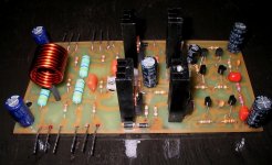
You can have any inductance value with any wire thickness...we use 1 to 3 milimeters thickness because they are easy to find, easy to make coils or (thick ones) they are mechanically resistant to continue having its shape even if you hit them with your arm, finger or any tool...you can make 2.2uh with any wire thickness, it is up to you to make it large or not large.... software offer mathematics calculation considering wire thickness, coil diameter, coil length and number of turns.
Image shows a picture with a small coil (more turns, small diameter) and other image shows a big coil, the one has less turns, thicker wire and large diameter.
regards,
Carlos
you can use a software i can send you...it is ony 1M size.
There are several coil calculator software around.... if you want this one them write to uncle charlie:
nanabrother@hotmail.com
carlos.eugenio1951@yahoo.com
Them i will send you the software.... there are some sentences you must translate to your language....but only a few sentences...see the image.
You can have any inductance value with any wire thickness...we use 1 to 3 milimeters thickness because they are easy to find, easy to make coils or (thick ones) they are mechanically resistant to continue having its shape even if you hit them with your arm, finger or any tool...you can make 2.2uh with any wire thickness, it is up to you to make it large or not large.... software offer mathematics calculation considering wire thickness, coil diameter, coil length and number of turns.
Image shows a picture with a small coil (more turns, small diameter) and other image shows a big coil, the one has less turns, thicker wire and large diameter.
regards,
Carlos
Attachments


Last edited:
From the printing on the Byron board it looks like a resistor goes through the middle of the choke, is that correct; and what value is it???
Thanks,
Thanks,
If the resistor has any magnetic material in it's construction (eg. Fe iron and others) then do not run it inside the coil (inductor).
Pass the resistance/s outside the coil to avoid (or at least minimise) any magnetic effect.
Since the resistor passes the HF, it should have the shortest route through the Network from amplifier to speaker. The inductor passes LF & MF and so can be offset from the shortest most straight route. If one is PCB mounting this part of the Thiele Network, then locating the resistor under the PCB in line with the traces would achieve the HF performance. Locate the inductor on standoffs (extended legs of the wire) on the topside of the PCB.
- Status
- Not open for further replies.
- Home
- Amplifiers
- Solid State
- Dx Blame MKIII-Hx - Builder's thread