Thanks, that explanation is clear. I have found that increasing OLG at my amp will also increase bandwidth, then I put bigger Cc to get lower BW. The effect isn't just lower BW, but also different phase lagging (slower) also a little slewrate degradation that affecting pulse response or squarewave response.
Phase lagging is important here in pulse response, while in sine response, it will only show different phase shift.
Phase lagging is important here in pulse response, while in sine response, it will only show different phase shift.
sorry for not reading all the posts...
have you concidered parasitic oscillations as a source of effects like "narrowing of sound stage"?
to my expierience they can do a lot of harm.
one could argue that lo feedback systems might be less prone to parasitic oscillations, and thus are more easily/frequently percieved as "better sounding"
This made me think of something else:
If you have RF coming in through the output, which is very common because many speaker cables and some speakers (e.g. ribbons and planars) make great antennas, then a lower impedance in the feedback path (i.e. more feedback) would allow more of the RF to reach the inputs.
The effects of the RF could be very complicated to understand; i.e. maybe not as simple as just inducing a demodulated AM signal after PN junctions. It could simply rectify into DC and change some internal operating points, in subtle (or not) ways. Or who knows? And ambient RF levels can vary a lot by location and time (and would likely even be different for left and right channels), making any diagnosis or trend more difficult to ascertain.
The late, great Al Sekela advocated (over in the Planar Speaker Asylum) inserting a high-currrent 10 uH RF Choke in series with Magnepan speakers' ribbon and planar foil tweeters, to keep RF from getting back into the amplifier, and many, many users reported a dramatic improvement in soundstage, clarity, and even bass response.
So maybe everyone here is correct but the problem's root cause lies elsewhere!
The suggested RF Chokes (inductors) are very low cost and can handle 20 amps of current and have DC Resistances (DCR) of around 0.005 Ohms:
Bourns/J.W. Miller 2301-H-RC (and 2301-V-RC) are currently $3.99 qty 1 or $2.99 qty 10. See at mouser.com: Mouser Electronics - Electronic Component Distributor 542-2301
[Edit:] Actually, Al Sekela suggested the 5522-RC (20 Amps, .006 Ohms, $5.73) or 5502-RC (9 Amps, .017 Ohms, $3.90) models. He explained it here: http://www.integracoustics.com/MUG/MUG/tweaks/Al_Sekela.html .
I guess that any other similarly-rated RF chokes should work as well.
Maybe some of the people who have demonstrated to themselves that removing feedback improves their soundstage should try replacing the feedback and adding these chokes in series with their outputs. (And those of us who are using feedback could also try adding the chokes in series with our outputs.) It seems like it would be difficult to set up a good scientific experiment, for this, since the ambient RF would need to be controlled, but maybe a trend could be found.
Tom
Last edited:
Thanks, that explanation is clear. I have found that increasing OLG at my amp will also increase bandwidth, then I put bigger Cc to get lower BW. The effect isn't just lower BW, but also different phase lagging (slower) also a little slewrate degradation that affecting pulse response or squarewave response.
Phase lagging is important here in pulse response, while in sine response, it will only show different phase shift.
Yes, if you increase your Cc that immediately lowers the slew rate. The slew rate depends on the input stage bias current and the Cc value, so to compensate you would need to increase input stage current.
And of course different Cc means different phase shifts, although it is not really correct to identify phase shift with 'slow' or 'fast'.
jan didden
This made me think of something else:
If you have RF coming in through the output, [snip]Tom
Good point Tom. I looked up those chokes and they are 10uH. I believe most people would use an output choke in their amps anyway, but these are often something like 3-6uH. And Iwould recommend air coils anyway, I wouldn't put a magnetic part in my speaker lead!
jan didden
Tom,
I found 3.3nF across the Magneplanar inputs fixed the RF pickup issue neatly. The amp was fine with this low value, and the cap was cheaper and easier.
I found 3.3nF across the Magneplanar inputs fixed the RF pickup issue neatly. The amp was fine with this low value, and the cap was cheaper and easier.
It was said that the TDA1547 is a poor DAC from the early 90s. It was claimed it could be blamed for potentially bad sound and that critical reviews could be found easily. But thats wrong.
I know todays high-end chips are better in all measurements. But the TDA1547 is not so bad. At 1993 it was one of the best DAC chips. And even today there are a lot of people who like the TD1543 till TDA1547 series. Ok, this is a subjective point of view.
Also,
I think the DAC TDA1547 doesn't affect anything here, for the simple reason, that only the opamp has been changed and there is no distorting interaction between DAC and opamps.
The second point,
It is wrong that of every amp the response and phase-curve follows a Hilbert curve or transformation. For example look in the internet at the datasheets of the OPA2134 and the NJM2068.
Or the OPA2134 with OPA2111.
Last edited:
It is wrong that of every amp the response and phase-curve follows a Hilbert curve or transformation. For example look in the internet at the datasheets of the OPA2134 and the NJM2068.
Or the OPA2134 with OPA2111.
Really?
And of course different Cc means different phase shifts, although it is not really correct to identify phase shift with 'slow' or 'fast'.
Slow is about its response. When they always work in OL, right? Then OL phase shift is used, it is phase difference between input and output by amp lagging.
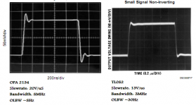
Here are some pic from OPAmp datasheet, OPA 2134 isn't even better than TL082 for buffering DAC, and may be NJM4565 has better response also better current for driving capacitive loads for passive filtering. Sadly NJM datasheet just too simple.
@ChPlus
What not follow Hilbert curve you means?
Attachments
Last edited:
I guess that any other similarly-rated RF chokes should work as well.
I can't quite figure out why in the pic, the choke is at the speaker end rather than the amp end. If the cables pick up RF (and I'm sure they do) wouldn't it make more sense to have the choke at the amp's speaker outputs? Also why not try a common-mode choke? - it would be possible to have a higher common-mode inductance that way, for a smaller size. Then the linearity of the ferrite is much less of an issue too because the differential-mode inductance will be greatly reduced.
I dont know what the C and L of the Magnaplana's are, but it may well be that the choke is actually doing something else here . . . .
If you have heard an amp that is oscillating, it sounds like hash (SHSHSHSHsssssshshsh etc etc). If you touch or move the speaker cables, you can often reduce it, or make it sound different.
So, maybe the coil is not actually killing 'RF'pickup, but sorting out a marginally stable amp, of which there are many.
Yeah good point. So a CM choke would actually serve to distinguish between those two conditions - if the sound quality improvement doesn't happen with it, your hypothesis is to be preferred 🙂
Tom,
I found 3.3nF across the Magneplanar inputs fixed the RF pickup issue neatly. The amp was fine with this low value, and the cap was cheaper and easier.
Probably not so much a filering effect but simply moved the tank circuit frequency to where there was no so much RF to be picked up.
I can't quite figure out why in the pic, the choke is at the speaker end rather than the amp end. If the cables pick up RF (and I'm sure they do) wouldn't it make more sense to have the choke at the amp's speaker outputs? Also why not try a common-mode choke? - it would be possible to have a higher common-mode inductance that way, for a smaller size. Then the linearity of the ferrite is much less of an issue too because the differential-mode inductance will be greatly reduced.
Yeah, I immediately thought about that, too, and think that in general that should be better. But maybe most people use shielded or twisted speaker cables and they aren't picking up much RF? The planar and ribbon tweeters, on the other hand, are probably terribly-great RF antennas. And it would also be much easier for many Magnepan owners to insert the choke on the speaker end of the cable, since many Magnepan speakers have accessible rear connections for a series "tweeter attenuator", which are typically unused. (Oh. also, the mid-bass drivers usually (or maybe always) have a much larger choke in series, already. That doesn't help if the cable is an antenna, but explains why they only put them on the tweeters.)
As Jan Didden mentioned, it should also be much better to use air-core coils. And he's no-doubt correct that the value should be between 3 and 6 uH, instead of 10 uH. I also noticed that some people preferred the sound of 5 uH over 10 uH.
Hugh's (AKSA's) suggestion of 3.3 nF across the Magnepan inputs is interesting, too. I'm going to try that, too.
And what about Bonsai's hypothesis about the improvements actually coming from amplifier stabilization effects rather than RF filtering? Could be, I suppose. But a lot of the "testimonials" about this tweak are from people with very famous types of amps so it's hard for me to imagine that they were all marginally stable. (But you never know!) The C and L of the magnepans are probably quite low. All the drivers are is wire or foil glued to mylar, except in the case of the true ribbon tweeters in certain models.
Tom
Last edited:
But maybe most people use shielded or twisted speaker cables and they aren't picking up much RF?
I dunno - if they're using twisted then the pair (taken together, common-mode) is gonna be as good an antenna as a single wire. If they're using coax, then the screen is a great antenna too. So they'd have to be using screened twisted with the screen returned to some benign ground point (not the amp's -ve speaker output). Can't see it happening myself in audiophilia 😉
[OT]
It's by far not that easy, Jan. I have ten years of private research on those matters on my back (manipulation of phantom source properties, and manipulations for both individual tracks as well as fully mastered music).
BTW, some % of positive crosstalk also does generally broaden the soundstage, mostly in depth and height, and creates "bigger" phantom sources (with any material containing close "copies" of a signal in the L/R-channels and a interchannel delay between them). Comb filters triggering HRTF-based localization cues, generally speaking...
-Klaus
[/OT]
So far to me your post is the most pin point to the topic at hand - *but* - it certainly will take another few years to make people aware of the fundamental difference between min phase versus consecutive min phase behaviour
Everyone likes to go on and on again about what is the basics of mere Kirchhoff (Gustav Robert, anno 1845) & Bode (Hendrik Wade, anno 1930) - they just feel (more) save this way
🙂
Michael
Last edited:
Slow is about its response. When they always work in OL, right? Then OL phase shift is used, it is phase difference between input and output by amp lagging.
Here are some pic from OPAmp datasheet, OPA 2134 isn't even better than TL082 for buffering DAC, and may be NJM4565 has better response also better current for driving capacitive loads for passive filtering. Sadly NJM datasheet just too simple.
@ChPlus
What not follow Hilbert curve you means?
What it the point of your post? What are you demonstrating by showing the pulse response of these opamps?
Do you realise that for audio signals these responses follow any possible audio transient exactly to the nano second?
jan didden
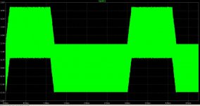
We can see here the "perfect" opamps myth. Here , we have a standard, real implementation of the goog opamp, LT1028. We have a little input parasitic capacitance, 50pF and a capacitive load, 200pF and 500nH inductive load. We have 1V and 100khz step signal at input of opamp.
Attachments
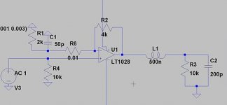
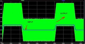
We can see here the "perfect" opamps myth. Here , we have a standard, real implementation of the goog opamp, LT1028. We have a little input parasitic capacitance, 50pF and a capacitive load, 200pF and 500nH inductive load. We have 1V and 100khz step signal at input of opamp.
Well, yes, you created an unstable circuit. What is your point? That electronic circuits can be unstable??
jan didden
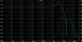
Yes, that-s my point. In fact, the most important is it how you implement a real schematic. What u see in my first post, it is a real schematic with parasitic component. So, I was adding a 100ohm resistor to the output of a opamp and...... nothing... the circuit it is unstable again. We have a big problem in this moment.
Attachments
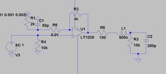
Well, most op amp ap notes speak about how important it is to keep the capacitance to ground at the inverting input low to avoid just the kind of problem you highlight above . . . yet, so many times people just ignore that. And, the faster the op-amp, the more critical the layout. Having said that, 50pF is quite high. What you might want to do is show the kind of overshoot and ringing you can get with just moderate amounts of capacitance from the inverting input to ground. Same principles apply BTW to discrete circuits, but the lower loop gain, and generally lower GBW mean the problem is not seen as much (and no, this does not mean 'feedback' and IC op-amps are bad . . . . it just means you need to use them properly!)
- Status
- Not open for further replies.
- Home
- Amplifiers
- Solid State
- Feedback affects Soundstage, Imaging, Transients ?