Ringing in a badly terminated video or VGA line is certainly visible - as we discussed years ago. But that has a bandwidth in the MHz.
While it is true that so-called transmission line effects do not come into play in the audio band because of the lengths involved, it IS true that transmission line effecst come into play at higher frequencies in the low MHz range where an amplifier may still have its feedback active. This can destabilize some amplifiers. Note that we are not just talking about the lumped capacitance of the speaker cable.
Hi Bob,
You mention two distinct issues, both related.
T-line effects do indeed come into play in the audio realm, but in a non-obvious way. Standard smith charts, standing waves and ratio, all completely fall apart at these wavelengths..
Using a bounce model to establish the low pass nature of the t-line/low z load is significant only in establishing the delay the system can cause. This delay is dependent on the line to load ratio. AND, this delay is essentially zero when line equals load.
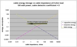
Way up in frequency, with gain still available, the unloaded (open termination) t line will look like a capacitor. graph attached..
Of note is how the line stores energy as a result of the impedance of the load. For open or high z load, the nature of the line storage is capacitive. For shorted or low load z, the nature of the line storage is inductive.
When the load z equals the line z, the nature of the line is that of pure resistance. And, at that point, the inductive energy stored is exactly equal to the capacitive energy storage.
Cheers, jn
Attachments
Last edited:
I'll only agree as far as "Should not." I have seen audio power amplifiers with output on the speaker terminal of several volts at one MHz or so. Two out of a batch of 80!
You're talking about things that are probably broken again (or at least take a look at what's wrong).
I still remember the TAS reviewer that told me it ended up one of the amps he reviewed was oscillating due to his exotic cable. He let the review stand saying you can't hear 60MHz anyway.
Last edited:
You're talking about things that are probably broken again (or at least take a look at what's wrong).
I still remember the TAS reviewer that told me it ended up one of the amps he reviewed was oscillating due to his exotic cable. He let the review stand saying you can't hear 60MHz anyway.
Scott,
We can never agree, bad design yes, out of spec, no. I had enough clout that I returned those two and got different units that did not show the same behavior.
We might agree that RF at the output can affect the feedback input and cause artifacts. I usually notice an increase in noise floor from amplifiers that have an RF issue.
ES
Scott,
We can never agree, bad design yes, out of spec, no. ES
Come on Ed, what is the use of talking about defective units and the general theory of what is going on?
This coils is not here to stop the RF produced by the amplifier, but for two reasons:There is a reason for the inductor in the output leg of many solid state amplifiers. Looking around with an RF probe does every so often turn up amplifiers that create RF energy sometimes as high as 500 MHz!
So let me claim so audio amplifiers do generate RF! (And some surprising name brands!)
1- Never allow charge impedance to go under a fixed value and turn the phase (Satisfy the Nyquist law and keep the amplifier stable when the load can be highly capacitive, some electrostatic loudspeakers are pretty good for that ). In other words, this coil is not there to stop the RF produced by the amplifier, but to avoid-it from producing them, acting like an oscillator, and keep the amplifier stable.
2- Stop RF from the speaker cable, acting like an antena, to come in the feed-back loop. (good practice).
Last edited:
Hi,
The job this coil, commonly in parallel with a low value resistor, does on stopping RFI seems at best a lot worse than the job that London's finest did so far for the last three nights in stopping riots and looting.
Ciao T
PS, looking at the news, make that four nights.
This coils is not here to stop the RF produced by the amplifier, but for two reasons:
....
2- Stop RF from the speaker cable, acting like an antena, to come in the feed-back loop. (good practice).
The job this coil, commonly in parallel with a low value resistor, does on stopping RFI seems at best a lot worse than the job that London's finest did so far for the last three nights in stopping riots and looting.
Ciao T
PS, looking at the news, make that four nights.
Hi,
The job this coil, commonly in parallel with a low value resistor, does on stopping RFI seems at best a lot worse than the job that London's finest did so far for the last three nights in stopping riots and looting.
Ciao T
PS, looking at the news, make that four nights.
Bad news, the media is playing up the effect of social media at every turn, I'm glad my cell phone sits discharged in my bag.
This coils is not here to stop the RF produced by the amplifier, but for two reasons:
1- Never allow charge impedance to go under a fixed value and turn the phase (Satisfy the Nyquist law and keep the amplifier stable when the load can be highly capacitive, some electrostatic loudspeakers are pretty good for that ). In other words, this coil is not there to stop the RF produced by the amplifier, but to avoid-it from producing them, acting like an oscillator, and keep the amplifier stable.
2- Stop RF from the speaker cable, acting like an antena, to come in the feed-back loop. (good practice).
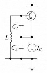
Attached is a deliberate oscillator. C1 is built into the transistor, C2 is the output leads and L can be the PC trace or in some amplifiers the wires from the PC card to the output transistor base.
It is easy to get this in the output stages of a solid state amplifier. If you have ever looked at the output of such an amplifier without the RC network load it is common to see the oscillations. The very small values of inductance used are often well outside of the bandwidth of the entire amplifier, but not the outputs!
The values are also too small and with out load on the feedback side to be of much use in RF protection.
Scott,
The manufacturer only recently stopped making these units and never considered this a defect! It was outside what they thought anyone would care about and was never cited by the FCC!
One of our bench tests when we evaluate a new amplifier is to look at the output well into RF frequencies. About half of the amplifiers we run that test on show RF output!
ES
Attachments
Did-you mean this amplier is not stable without any load ? What is the use of this resistance ? The coil you are talking about is highly resistive ? And, so, this amplifier has a very low damping factor ?The job this coil, commonly in parallel with a low value resistor
I would like to replace this thread in the topic.
So, and for the non RF specialists readers, i will take the 'Candid' position.
Considering a common amplifier, with a damping factor >200 on a 8 ohm load at 100hz, his impedance increasing with frequency after, let say 1000hz. Considering a common enclosure, with impedance curve varying from 3 ohms around 50hz to, let say 50 ohms at 20 000hz, or 8 ohms, if the tweeter is compensated), and a loudspeaker cable of , let say, 5 meters, did we have, in the 20- 40 000hz (what a fast tweeter 🙂 ) to consider transmission lines effects. (other than DC resistance of the cable) ?
If the response is positive, what will be the scale of the linearity and harmonic (if any) distortion ?
Hi,
I meant what I typed...
Normally the output inductor is paralleled with a low value resistor, for a variety of reasons.
Even if the resistor is not present, the actual inductors used in amplifiers block RFI a lot less than than a London Metropolitan Police line on a lazy tuesday afternoon...
Ciao T
Did-you mean this amplier is not stable without any load ? What is the use of this resistance ? The coil you are talking about is highly resistive ? And, so, this amplifier has a very low damping factor ?
I meant what I typed...
Normally the output inductor is paralleled with a low value resistor, for a variety of reasons.
Even if the resistor is not present, the actual inductors used in amplifiers block RFI a lot less than than a London Metropolitan Police line on a lazy tuesday afternoon...
Ciao T
If i have time to make measurements on my high speed current feed-back amplifier (> 2mhz bandwitch) and photos of my oscilloscope, i will prove you the contrary.Even if the resistor is not present, the actual inductors used in amplifiers block RFI a lot less than than a London Metropolitan Police line on a lazy tuesday afternoon...
(By PM, it is out of topic)
Last edited:
Esperado, Thorsten is correct, the coil does little to reduce RF, the paralleled resistor does do something useful, but many designers do not use either, anymore. Yet we can make stable, fast, powerful, amplifiers.
The coil/resistor doesn't block RF. It also doesn't wash your car or remove your tonsils. Blocking RF isn't its intended function. If you need to block RF (and I have never needed to do that in a domestic system using non-pathological amplification), there are many good ways to do that. The CR is for stability with oddball loads, as you well know.
The coil/resistor doesn't block RF. It also doesn't wash your car or remove your tonsils. Blocking RF isn't its intended function. If you need to block RF (and I have never needed to do that in a domestic system using non-pathological amplification), there are many good ways to do that. The CR is for stability with oddball loads, as you well know.
And how far are you from a grandfathered in 24 hour clear channel AM station? You get the freakin' radio on everything! Then the friend who lived by the TV station's transmitter found if he wrapped the TV in aluminum foil and included space to get his head in, could actually get a signal!
Then there was the New Yorker who lived so close to all of the transmitter he used florescent light bulbs just by themselves for illumination. When asked how he turned out the lights he replied "Simple!" and then placed the glowing tubes in a closet and shut the door.
Most folks won't have the problem often, sometimes just when a trucker goes by. Some folks never, but the problem can be a killer for others.
RF in the speaker wire can be a problem and is often mistaken for something else. So weird wire may do some folks some good, although there are less expensive more effective solutions if the problem is recognized and addressed.
I cannot understand such abstracts ('do something useful') and generalizations. I never use such coils to cure bad designed shematic. I use-it on my amplifier just to reduce RF returns and get nice square waves at 20 000hz with a "non transmission line" accorded cable. But my amplifier is rock stable with or without, even on high capacitive loads (do not use any parallel cap in the feedback loop). The impedance of the output stays very low up to quite high frequencies, and the coil DO reduce very high frequencies HF returns. Believe-me please, i had designed, soldered and tuned all the stuff by myself ;-)Esperado, Thorsten is correct, the coil does little to reduce RF, the paralleled resistor does do something useful, but many designers do not use either, anymore. Yet we can make stable, fast, powerful, amplifiers.
Last edited:
And how far are you from a grandfathered in 24 hour clear channel AM station?
See post 21. Like 99% of the world, I am not living in the shadow of an AM station.
So weird wire may do some folks some good, although there are less expensive more effective solutions if the problem is recognized and addressed.
Bingo. No need to make wire mystical.
I would like to replace this thread in the topic.
So, and for the non RF specialists readers, i will take the 'Candid' position.
Considering a common amplifier, with a damping factor >200 on a 8 ohm load at 100hz, his impedance increasing with frequency after, let say 1000hz. Considering a common enclosure, with impedance curve varying from 3 ohms around 50hz to, let say 50 ohms at 20 000hz, or 8 ohms, if the tweeter is compensated), and a loudspeaker cable of , let say, 5 meters, did we have, in the 20- 40 000hz (what a fast tweeter 🙂 ) to consider transmission lines effects. (other than DC resistance of the cable) ?
If the response is positive, what will be the scale of the linearity and harmonic (if any) distortion ?
Take your amplifier with a signal generator, square wave..set the output to 4 volts maximum.
Use a 4 ohm non inductive resistive load.
Use a simple wire pair, #14awg spaced 1 inch apart, length of 4 meters.
Examine the risetime at the load.
Twist the wire pair together, examine the risetime. this is approx 100-120 ohms Z cable.
Use two twisted pair in parallel, this is about 60 ohms. Examine the risetime.
Use four twisted pairs, this is about 30 ohms. Examine the risetime.
Plot the risetime vs the cable impedance. Note that as the cable impedance lowers, the risetime is faster.
Repeat this for a load of 30 ohms. You will note that the risetime is fastest at this load when you use the four twisted pairs.
Cheers, John
- Status
- Not open for further replies.
- Home
- General Interest
- Everything Else
- speaker cable myths and facts