Check out this one ....
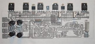
Finished the "new one" .. (below)
red= +60V
blue= -60v
green= earth/0V
dark yellow= MUSIC - AC
pink= jumper / or top trace double sided.
I like this better than the last and can see why the full low THD of this amp might be better represented by this "style".
Comments welcome - especially Andrew T's. 😀
To Variac - sorry about the constant changes , but this will insure a "winner" , not just another Ebay class attempt at an amp. This is commercial quality (ADCOM , LUXMAN, Harmon-kardon) similar style of layout and grounding. 😎
OS
Attachments
Last edited:
Hi OS looking very good.
Is there any advantage to having a left and right board (almost a mirror), so each when mounted in the case have the inputs at one end and power connections at the other? This would keep the power supply wiring short and out of the way of the input and output, assuming these are mounted either side of a case.
But that would increase cost a little of producing two boards rather then just one.
Cheers
Rob
Hi,
the -ve smoothing/decoupling cap has one connection. Prior to that there is a tapping after the fuse to feed power to the collectors.
That collector feed must be manoeuvred round to tap into the capacitor -ve pin.
Can I make one last request. Yes, really the last one.
Can you add in multiple pin pitch options to all, or at very least almost all, capacitors?
Last edited:
Hi,
1 .the -ve smoothing/decoupling cap has one connection. Prior to that there is a tapping after the fuse to feed power to the collectors.
That collector feed must be manoeuvred round to tap into the capacitor -ve pin.
Can I make one last request. Yes, really the last one.
2.Can you add in multiple pin pitch options to all, or at very least almost all, capacitors?
1. look below , I re-routed the negative rail tap directly to the cap. 🙂
2. What I did , was to look at both mouser and digikey .... find the cheapest and most common lead spacing for all the components.
A. Electrolytics - all 7.5 , 5 , 3.5mm standard. Main decoupling = 7.5mm - 330uF@100v all the way to 1Kuf @ 63V , smaller input stage decoupling - 5mm lead space - 100uf@100v to 470uf@ 63v ..... the 2- 3.5mm electrolytics should be 22uf@ 63-100v. All caps face the same direction - cuts down on errors. I might add 10mm pitch for the big caps.
I will give a few part #'s in the BOM.
B. All the poly film caps are the most common thin 10mm ones , except for 2-7.5mm ones (input filter 220pF and the .1uf dc blocking next to the 220u NP).
All VERY common , mouser has 20 different manufacturers making them.
C.LED's can be anything , just to keep safe - or omit them.
D. Main Emitter resistor's can be the 10-12mm small ones (common - OEM) or the 22mm big ceramics stood on end or with the leads formed.
E.All the other resistors can be anything , except for a few 1/2w units (VAS emmiter R's , driver Re , fuse safety R's). Current mirror and LTP resistors should be 1% , all others 2 or 5%.
All the parts are COMMON , I would just recommend ... DON'T BUY EBAY SEMI'S !!!
I will label and finish , still open for comment's and suggestions.
OS
Attachments
Hi OS looking very good.
Is there any advantage to having a left and right board (almost a mirror), so each when mounted in the case have the inputs at one end and power connections at the other? This would keep the power supply wiring short and out of the way of the input and output, assuming these are mounted either side of a case.
But that would increase cost a little of producing two boards rather then just one.
Cheers
Rob
$4-700 per lot. 2 boards would be "walking the plank" , cash wise. 😱
Having an extra 6-10" of 12-14 ga. wire going to one channel won't be too big a factor. I have a input cable going right across a trafo on my Nikko(this amp) , 0 hum ... absolute 0 ... can't even see it on a CRO , much less actually HEAR it. 😱
OS
Revision 2 done
Hopefully , there will not be any more cool ideas to incorporate 😀 .
Really , this is a bit different than the "standard" layout.
BTW , multiple lead pitches are on most of the film caps and electrolytics (7.5mm and 10mm) ... just about any cap will fit. 🙂
Below is what I will submit , the BOM-schematic , and any extra documentation.
I hope it will please (MOST) DIY'ers. 🙄 PS , the base circuit is the EXACT same , just smaller on-board capacitances.
I plan on using this layout style on my luxman triple , too - that is how confident I am with it's merits.
OS
Attachments
To get the power and input connections at the same end for each side builders could mount one channel upside down. Not pretty, but it is ideal wiring wise. Sucks for bias/offset adjustments though. That's how Ashly does it:
Just an idea for those that don't like the non-mirrored wiring for asymmetrical boards. I myself would be fine with it.
Just an idea for those that don't like the non-mirrored wiring for asymmetrical boards. I myself would be fine with it.
To get the power and input connections at the same end for each side builders could mount one channel upside down. Not pretty, but it is ideal wiring wise. Sucks for bias/offset adjustments though. That's how Ashly does it:
Just an idea for those that don't like the non-mirrored wiring for asymmetrical boards. I myself would be fine with it.
I think that is just "picky" ... just use 12 ga. "audiophile" wire (below). Even 3-400mm of it would not have much resistance/inductance.
Chassis - PS below is all set for either the DIYA AMP or the Luxman triple. 🙂
12 ga. rail wire and 14 ga. dual grounds.
OS
Attachments
Will it have any speaker protection circuit? If not, for the beginners' benefit, a link to some good design like the Harmon amp's protection ckt may be quoted.
Just a suggestion.
U never know how the beginner will make errors.
Gajanan
Just a suggestion.
U never know how the beginner will make errors.
Gajanan
speaker protection | eBay
70+ units , 7 -20$$. ta7317p , or discrete , all omron or similar relays. cheap.
OS
70+ units , 7 -20$$. ta7317p , or discrete , all omron or similar relays. cheap.
OS
Can I ask one more (not suggestion) rather request. Can you put B/W in PDF for home etching boards
thanks
thanks
Can I ask one more (not suggestion) rather request. Can you put B/W in PDF for home etching boards
thanks
Zip has .JPG PCB art , overview,schematic , and BOM.
JPG is non-mirror (toner transfer) and will (should) measure 254 X 76mm in a graphics program (PSP7 is what I use).
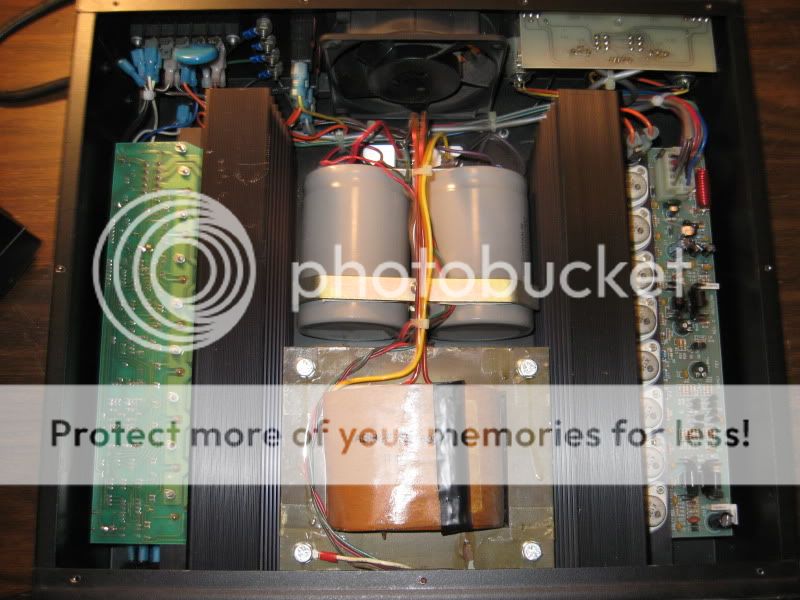
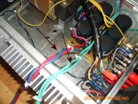
Picture of final "real world debug" below.
OS
Attachments
Last edited:
You are welcome , layout was tweaked after photo to give some of the caps more room.
Be careful , this is still "under review".
OS
Be careful , this is still "under review".
OS
I think this new layout is better. I had some concerns to be honest about the 0V rail between the two filtering caps and the possibility of EM induction noise into the circuitry running adjacent to that line. Nice one OS!
.
Be careful , this is still "under review".
OS
Nice job!
I notice a small error on the new layout: C1's furthest pad is not connected.
- Home
- Amplifiers
- Solid State
- diyAB Amp - The "Honey Badger"