Hi,
Do carefully check the physical sizes, if you can datasheets for impedance (and impedance minimum frequency). If you are running the DEM Clock very fast you need "fast" capacitors...
I guess you can. Where does this come from, out of interest?
I would say WS is probably too slow for DEM reclock. HpT recommends 4 * Fs at 4 * Oversampling IIRC, so 705.6KHz. In this case make sure that the decoupling capacitors have a minimum impedance at at least four times that frequency.
Doing this means that all DEM Elements will be used for a single sample.
This removes the error randomisation from running the two clocks without link, but at the same time removes the inevitable random errors that produces. It then minimises the systematic errors caused by variations in the DAC's "build in" errors, which is after all the main point of DEM.
Ciao T
Thorsten thanks for the reply.
I'll be changing caps then....have many spares and will apply the logic of the junk box ! 😀
Do carefully check the physical sizes, if you can datasheets for impedance (and impedance minimum frequency). If you are running the DEM Clock very fast you need "fast" capacitors...
Pic 2 - is this another DEM option using WS.
Can I feed 2.8 mhz to pin 16 this way then remove the 470pf styrene cap that connects 16 to 17 and then gnd 17 ?
I guess you can. Where does this come from, out of interest?
I would say WS is probably too slow for DEM reclock. HpT recommends 4 * Fs at 4 * Oversampling IIRC, so 705.6KHz. In this case make sure that the decoupling capacitors have a minimum impedance at at least four times that frequency.
Doing this means that all DEM Elements will be used for a single sample.
This removes the error randomisation from running the two clocks without link, but at the same time removes the inevitable random errors that produces. It then minimises the systematic errors caused by variations in the DAC's "build in" errors, which is after all the main point of DEM.
Ciao T
I don't see it in the AMRHi,
Probably. You just need the correct frequency for the DEM Reclocking derived from the BCK.
I use 4.7uF Wima MKS (Mylar) on the two MSB's, 1uF Wima MKP's (Polyproplylene) inbetween and Wima 0.47uF MKC's (Polycarbonate) for the LSB's, they where in my junkbox and fitted the PCB... 😉
I like it well.
Ciao T
Hi,
For AMR I used a much better layout than was used for what is playing at home (not really my design originally, even if it is now), super low inductance SMD Film Cap's and Os-Con's on the MSB's... The DEM Reclocking is much faster for that one due to this.
I commented on this above.
Ciao T
I don't see it in the AMR
For AMR I used a much better layout than was used for what is playing at home (not really my design originally, even if it is now), super low inductance SMD Film Cap's and Os-Con's on the MSB's... The DEM Reclocking is much faster for that one due to this.
I commented on this above.
Ciao T
Please read post 2738 from John
http://www.diyaudio.com/forums/digi...e-nos-dac-using-tda1541a-274.html#post1784706
http://www.diyaudio.com/forums/digi...e-nos-dac-using-tda1541a-274.html#post1784706
Hi,
Looking at the internal structure of the TDA1541A, the MSB's Filter caps can tolerate all sorts of levels of leakage (as long at it applies to both pins per channel) as it is the "master" for the whole divider chain...
Ciao T
Please read post 2738 from John
http://www.diyaudio.com/forums/digi...e-nos-dac-using-tda1541a-274.html#post1784706
Now I am confused as ECdesigns MK4 schematic has all bit decoupling caps of 47nF value. And in the Mk7 they are all 1uF.....
http://www.diyaudio.com/forums/digi...e-nos-dac-using-tda1541a-366.html#post2549175
Last edited:
Hi,
Looking at the internal structure of the TDA1541A, the MSB's Filter caps can tolerate all sorts of levels of leakage (as long at it applies to both pins per channel) as it is the "master" for the whole divider chain...
Ciao T
Really?
Attachments
In my experience, the end/MSB-caps has the greatest influence, and larger of same type gave more bass..(!) (like changing from 1uF to 4,7uF, - I think I settled on 2,2uF here) (AYA-DAC)
Arne K
Arne K
Hi,
Do you have a PC with SPDIF output or a CD-Player and some test CD's, plus a 'scope (nothing fancy, 20MHz analogue 'scope should do, 60MHz or 100MHz is a Bonus)? I think you take some readings.
For SPDIF, look at the CS8412/8414 Datasheet and use the simplest configuration given, remove the transformer (at least untill you have the tools and knowledge to correctly implement it).
For DEM Reclocking, there is plenty of information on this board.
Ciao T
Thanks for the suggestions, but I only have a scope voltmeter going up to 1khz.
I changed the configuration of the input and verified everything again. No change at all. Readings on the output of tda1541 are at 0mv.
Removing the SAA and using only the clock and 74hc4040 is my next step.
Then I will post again.
In my experience, the end/MSB-caps has the greatest influence, and larger of same type gave more bass..(!) (like changing from 1uF to 4,7uF, - I think I settled on 2,2uF here) (AYA-DAC)
Arne K
Interesting - does ' gave more bass ' mean your speakers are now capable of going lower than their rating ?
Like 40 hz before the tweak to 25 hz ?
What does all this mean 😕
Hi,
Really. Just get the whole schematic for TDA1541.
Ciao T
Really?
Really. Just get the whole schematic for TDA1541.
Ciao T
Hi,
You can get pretty decent older 'scopes on e-bay for little money. There are also some new Chinese Rigol OEM version digital scope's that are not all that bad and not expensive.
Getting one and learning to use it while troubleshooting this DAC will ber very useful in the long run.
I can DIY without an AP2 just fine (I have one in the office though), but without a scope? It's like trying to shoot a small target over a long distance with a sniper rifle blindfolded...
It may better to get the basics working first and then to try other things.
Ciao T
Thanks for the suggestions, but I only have a scope voltmeter going up to 1khz.
You can get pretty decent older 'scopes on e-bay for little money. There are also some new Chinese Rigol OEM version digital scope's that are not all that bad and not expensive.
Getting one and learning to use it while troubleshooting this DAC will ber very useful in the long run.
I can DIY without an AP2 just fine (I have one in the office though), but without a scope? It's like trying to shoot a small target over a long distance with a sniper rifle blindfolded...
Removing the SAA and using only the clock and 74hc4040 is my next step. Then I will post again.
It may better to get the basics working first and then to try other things.
Ciao T
Hi,
Really. Just get the whole schematic for TDA1541.
Ciao T
OK
Attachments
Hi Andrew,
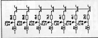
AFAIK the DEM circuit you posted was used in the Grundig CD9000.
I tried this circuit, connecting the 2K2 resistor to pin 1 (BCK). A quick listening test showed that it worked fine. Has anybody checked with a scope if the DEM oscillator is locked to BCK? Why do you want to ground pin 17?
AFAIK the DEM circuit you posted was used in the Grundig CD9000.
I tried this circuit, connecting the 2K2 resistor to pin 1 (BCK). A quick listening test showed that it worked fine. Has anybody checked with a scope if the DEM oscillator is locked to BCK? Why do you want to ground pin 17?
Sandor Hi
erm....yes ' ground pin 17 ' comment was not my finest moment !!😱
I would not do this now having done more reading😀 !!!
Thorsten did not laugh or slap me either - which was nice of him !!
I'm currently locking DEM oscillator to BCK with a 250pf cap across pins 16 - 17 and it seems to work very well too !!
ecdesigns suggested this on a different thread / topic. He's very knowledgeable on the TDA 1541A in nos - even though I'm oversampling.
Can you describe ' worked fine ' in your case ?
I want to try proper DEM mod using 2.8 mhz clock feed ( which I have spare on my master clock )
Just unsure of what to do at the moment.
I need it absolutely clear in my head before I start this !!
Andrew
Hi,
I looked at the schematics (link : http://www.diyaudio.com/forums/digital-source/30025-decoupling-tda1541a-9.html#post2622805):
1. The OS tda LE/WS is connected to WABD of the saa7220 and they added 4.7k to the +5 power supply , I don't see any reason, why this resistor ?
2. For the bit clock and dac clock in OS or No-os why the pin SCK of tda isn't connected to pin9 XSYS of the Saa7220, like it was supposed to work, instead of linking pin 2 and 4 like in the audionote/adagio dacs ?
Last edited:
Hi,
Not being nice at all, I simply missed it... 😉
In this case make sure your layout for decoupling around the TDA1541 (including ground) will not cause excessive problems at 2.8MHz. Just look at the various traces and capacitor dimensions (Datasheets for capacitors even better) ad have a reasonable guess at inductance. Then decide if you want to go as high as 2.8MHz. The logic will work this high, I seem to remember.
Personally, unless I'm using the SMD Film Cap's I use on the AMR Design and my own layout, with an analogue groundplane for the powersupplies and decoupling caps on one side of the PCB and a digital groundplane on the other side of the PCB, tied together at the AGND Pin, then I would not use use as high a frequency. The layout from ecdesigns also seems quite good. Most commercial players and DACS have poor to very poor layout in this area.
Using 4 * Fs (which in your case would 705.6KHz for 4 * OS) gives you more margin for layout issues etc, and still has four full DEM cycles per sample, which suffices if this stuff works at all... ;-)
Ciao T
erm....yes ' ground pin 17 ' comment was not my finest moment !!😱 I would not do this now having done more reading😀 !!!
Thorsten did not laugh or slap me either - which was nice of him !!
Not being nice at all, I simply missed it... 😉
I want to try proper DEM mod using 2.8 mhz clock feed ( which I have spare on my master clock )
In this case make sure your layout for decoupling around the TDA1541 (including ground) will not cause excessive problems at 2.8MHz. Just look at the various traces and capacitor dimensions (Datasheets for capacitors even better) ad have a reasonable guess at inductance. Then decide if you want to go as high as 2.8MHz. The logic will work this high, I seem to remember.
Personally, unless I'm using the SMD Film Cap's I use on the AMR Design and my own layout, with an analogue groundplane for the powersupplies and decoupling caps on one side of the PCB and a digital groundplane on the other side of the PCB, tied together at the AGND Pin, then I would not use use as high a frequency. The layout from ecdesigns also seems quite good. Most commercial players and DACS have poor to very poor layout in this area.
Using 4 * Fs (which in your case would 705.6KHz for 4 * OS) gives you more margin for layout issues etc, and still has four full DEM cycles per sample, which suffices if this stuff works at all... ;-)
Ciao T
Hi,
I looked at the schematics (link : http://www.diyaudio.com/forums/digital-source/30025-decoupling-tda1541a-9.html#post2622805):
1. The OS tda LE/WS is connected to WABD of the saa7220 and they added 4.7k to the +5 power supply , I don't see any reason, why this resistor ?
2. For the bit clock and dac clock in OS or No-os why the pin SCK of tda isn't connected to pin9 XSYS of the Saa7220, like it was supposed to work, instead of linking pin 2 and 4 like in the audionote/adagio dacs ?
invalid link
- Status
- Not open for further replies.
- Home
- Source & Line
- Digital Source
- decoupling TDA1541A