which inductor do you use ? Model and supplier ?
RM10 with airgap for amp. There are from old power supply.
I have to make more tests, for now it looks good.
24vdc
5ohms load
24W output
Oscillating at 150KHz
YouTube - firtst test audio amp d
I hope get about 200W with this board.
24vdc
5ohms load
24W output
Oscillating at 150KHz
YouTube - firtst test audio amp d
I hope get about 200W with this board.
Last edited:
150k is too low for full range audio
Yes.It´s slow , I´m working on.
It has gone up to 230KHz with other version and inductor cores.
Attachments
what is your industor size and output cap anyway?
but if you use many slow parts like very big fets and so on, you will have hard time getting high freq. I have 30uH and 470nF LFP filter and I have no problems going over 600kHz with it, so I I lower it to 480k or so
but if you use many slow parts like very big fets and so on, you will have hard time getting high freq. I have 30uH and 470nF LFP filter and I have no problems going over 600kHz with it, so I I lower it to 480k or so
I have the t106-2 core at 11uH , other core at30uH , other inductor 22uH .
The capacitor is at 1uF , other version it has 1.5uF
-----------------------------------------------------------------------
The smd version has 30uH inductor,1uF capacitor.
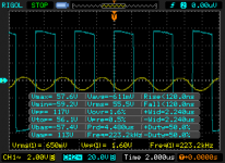
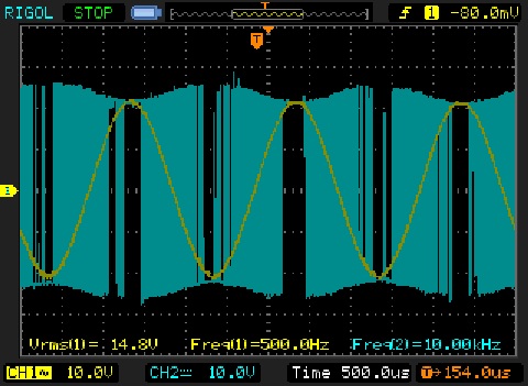
Now i got 45Watts at clippling limit at 20vdc with 5ohms load.
Vrms=14.8
R=5ohms
P= (V*V) / R
The capacitor is at 1uF , other version it has 1.5uF
-----------------------------------------------------------------------
The smd version has 30uH inductor,1uF capacitor.
Now i got 45Watts at clippling limit at 20vdc with 5ohms load.
Vrms=14.8
R=5ohms
P= (V*V) / R
Attachments

Last edited:
Amplifier run approximately on 250Khz with small noise. How I can start oscillate amplifier without signal? Because when I turn on, amplifier not oscillate.
I have the same problem,it does not start to self oscillate without signal input or at low volume.
It starts to work when I turn up the volume , it looks like a kind of trigger level.
😕😕😕
Any suggestion ??
ty!
hello guys,try to implement a RC filter at output like 470nF+10 ohm/2W in this way the amp allways has a load at output and will start to oscillate
It starts to work when I turn up the volume , it looks like a kind of trigger level.
😕😕😕
Any suggestion ??
There is a well known solution for this problem: it is needed to connect 30K-50K resistor between positive rail and inductor input (directly after mosfets).
The problem is that sometimes the input integrator wishes to start the oscillation with positive pulse, but the bootstrap capacitor for high side driver is not loaded yet. If we place the resistor between amp output and positive rail, then integrator will detect the positive error at startup and will start the oscillation with negative pulse, which will effectively charge the bootstrap capacitor.
I've been contemplating this build since it was posted, but I have one question (which might show my ignorance of this circuits operation). Is there a reason why the LM311 is powered by only +/-3V? Anything wrong with using a higher voltage?
I've been contemplating this build since it was posted, but I have one question (which might show my ignorance of this circuits operation). Is there a reason why the LM311 is powered by only +/-3V? Anything wrong with using a higher voltage?
The comparator has a finit slew rate. So higher votlage would need more time to change output stage.
Also the driven 2N5401 cannot take much higher voltage at its base.
The comparator has a finit slew rate. So higher votlage would need more time to change output stage.
Also the driven 2N5401 cannot take much higher voltage at its base.
I designed a similar amp with an LM393 comparator running off +/- 12 volts and it was fine. It was running at 250KHz ok.
The comparator has a finit slew rate. So higher votlage would need more time to change output stage.
Also the driven 2N5401 cannot take much higher voltage at its base.
Thank you lorylaci. 🙂
I designed a similar amp with an LM393 comparator running off +/- 12 volts and it was fine. It was running at 250KHz ok.
can you share schematic
can you share schematic
Use the same components as the other design and just run the comparator off +/-12v
Use the same components as the other design and just run the comparator off +/-12v
whats the benefit compare to LM311
whats the benefit compare to LM311
Probably no difference but I was just commenting that I found I could run my comparator off higher than +/- 3 volts.
I have one problem, my amp sometime starts beeping. I don´t know why. Can someone help me? 🙄
Where does the beep come from? from the speakor, or from the amp's component (like output inductor)?
Do you have two amp modules operating?
If you have two amps opereting there can be interference (mainly beacuese the two close carriers). Try plugging off the other amp module. If beep disappears then you should try to minimise interference. (filtering supply lines, ground connection redirection)
What is the swithcing freq of your supply and your amp modules?
Beep come from speaker. Yes I have two amps and when one plugging off then beep disappears. SMPS run at 75kHz and amp at 250Khz.
- Home
- Amplifiers
- Class D
- UCD 25 watts to 1200 watts using 2 mosfets