I would guess this switch is the one you want: SPST Round Rocker Switch w/Red Illumination 125VAC
I like the large DPDT switches myself (I use the 060-310). Bit of a pain to cut the hole though. The fuses you found should be OK.
Yep,
I dont care for illuminated switches myself.
But 12v switches are often for automotive work I guess.
DPDT Rocker Switch
hinted to by William...I find only one switch from that source that I would use.
DPDT will disconnect both legs of a circuit when not in use.
Rated 250VAC
hinted to by William...I find only one switch from that source that I would use.
DPDT will disconnect both legs of a circuit when not in use.
Rated 250VAC
Last edited:
DPDT Rocker Switch
hinted to by William...I find only one switch from that source that I would use.
DPDT will disconnect both legs of a circuit when not in use.
Rated 250VAC
How to connect or wire the DPDT with the transformer? When I built the ClassDAudio amplifier, it puts a SPST switch in series with the AC-L.
Thx!
Paro,
you should not allow yourself to wire up any mains powered project without trained supervision looking over your shoulder !!!!!
you should not allow yourself to wire up any mains powered project without trained supervision looking over your shoulder !!!!!
Check out this page for some direction on mains wiring. You certainly need to understand exactly what you are doing with this part of diy. The fun can come to a screeching halt real quick if you don't. And please be sure to use heatshrink tubing on all of the exposed terminals and connections.
Power Supply Wiring Guidelines
Power Supply Wiring Guidelines
These are good assuming you can reach round the back of your DCB1 to turn on and off.
MULTICOMP|JR-101-1-FRSG-02|INLET, IEC, DPST, WITH FUSE HOLDER | Farnell United Kingdom
MULTICOMP|JR-101-1-FRSG-02|INLET, IEC, DPST, WITH FUSE HOLDER | Farnell United Kingdom
Check out this page for some direction on mains wiring. You certainly need to understand exactly what you are doing with this part of diy. The fun can come to a screeching halt real quick if you don't. And please be sure to use heatshrink tubing on all of the exposed terminals and connections.
Power Supply Wiring Guidelines
These are good assuming you can reach round the back of your DCB1 to turn on and off.
MULTICOMP|JR-101-1-FRSG-02|INLET, IEC, DPST, WITH FUSE HOLDER | Farnell United Kingdom
Thanks! I have a good direction now.
I....guess....this could even be considered an alternative for a 12V power switch.
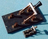
Sorry, AndrewT--you did an edit to my post, at the same time I was adding the photo I had forgotten to attach.......(!)
I really get concerned about some of these "wiring mains" questions...... opportunity for some serious injuries, or worse.....
I really get concerned about some of these "wiring mains" questions...... opportunity for some serious injuries, or worse.....
How can my reply including a quote from a post appear before that quoted post?
I live at 6,000 feet altitude. I think we have slower electrons here. 😀
Either that, or your PC is very, very, very fast......

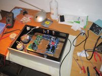
Nicely boxed, measures fine nothing to adjust, success. Let us know impressions later. Is your system lending to X1 gain?
Hod-Rod Question
Salas,
If I want to hod rod the DCB1, would the heat sink on the BOM sufficient?
Would the measurement any different between standard and hot-rod ones (like DC offset)?
Thanks!
Salas,
If I want to hod rod the DCB1, would the heat sink on the BOM sufficient?
Would the measurement any different between standard and hot-rod ones (like DC offset)?
Thanks!

Salas,
If I want to hod rod the DCB1, would the heat sink on the BOM sufficient?
Would the measurement any different between standard and hot-rod ones (like DC offset)?
Thanks!
No its not sufficient. Get 1C/W common sink per rail Mosfets or use a sturdy metal plate enclosure floor and mount Mosfets like in some power amps under PCB (like they do sit ups). Isolation pads are necessary when the Mosfets backs are on common metal resting place, else...smoke. Yes, they will measure a little different for current setting some times because Vgs of Mosfets changes with current and temperature. Also the audio Jfets can change offset a bit in a hotter environment. Anything under 5mV is not alarming.
Thanks Salas,
Hope so, I want to combine it with the F5 (also in progress). LS are Dynaudio S25. I know they are supposed to be thirsty but at the moment I am using them with a 14 yr old class A amp, 2 x 18 watt, loud enough.
The problem is mainly voltage gain. The F5 will need 2.5VRMS to give its rated power. With a buffer all this must be available from your source. Your other amp may well be more input sensitive although 7W weaker on 8R load. Do you know your source's voltage output?
@Salas,
I am using a previous version of the Linn Akurate DS. Here some specs from their website, since I don't know how to measure this:
Output voltage 2 V R R MS (0 dBFS , vol. 80)
The present amp is A-18, Hawk, designed by John van der Sluis, Netherlands, see scheme. No pre-amp just a 100k log pot.
I am using a previous version of the Linn Akurate DS. Here some specs from their website, since I don't know how to measure this:
Output voltage 2 V R R MS (0 dBFS , vol. 80)
The present amp is A-18, Hawk, designed by John van der Sluis, Netherlands, see scheme. No pre-amp just a 100k log pot.
Attachments
If the amp schema had values we could figure out the gain, has enough open loop gain to allow set it conventionally as far as the topology hints. To check any CDP's RMS output, a 0dB sine wave from a test CD (preferably below 1kHz) and a DMM set at VAC would show.
- Home
- Amplifiers
- Pass Labs
- Building a symmetrical PSU B1 buffer