Dear Lineup,
Thank you so much for all your hard work, I am one of the people who will benefit from your patient work with the amplifier.
I will be driving a pair of Mark Audio 4 ohm CHP-70's in Frugel Horn Mk3's and the 16V is just what I need.
I am very grateful to you.
Warmest wishes - Jim Read
Thank you so much for all your hard work, I am one of the people who will benefit from your patient work with the amplifier.
I will be driving a pair of Mark Audio 4 ohm CHP-70's in Frugel Horn Mk3's and the 16V is just what I need.
I am very grateful to you.
Warmest wishes - Jim Read
Yes, there is no change except to choose R1, R12 for ~1 A in output stage.
For 4 Ohm you may need a bit more than 1 A. Maybe 1.25-1.50A
It is easy to change supply voltage in Le Monstre to 2x16 Volt
For 4 Ohm you may need a bit more than 1 A. Maybe 1.25-1.50A
It is easy to change supply voltage in Le Monstre to 2x16 Volt
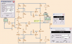
I made a 16 Volt 4 Ohm version.
See diagram.
The components in red are which adjusted.
- Added two extra 1 Ohm resistors
- Adjusted R1 and R12 for 1.5 Ampere bias.
4 Ohm speakers need more current than 8 Ohm
The output result is 14.64 Watt into 4 Ohm
at THD 0.300%
See diagram.
The components in red are which adjusted.
- Added two extra 1 Ohm resistors
- Adjusted R1 and R12 for 1.5 Ampere bias.
4 Ohm speakers need more current than 8 Ohm
The output result is 14.64 Watt into 4 Ohm
at THD 0.300%
Attachments
Hiraga with 4 ohm spearkers..
Hello Lineup..
As i want to use ti with batteries..
Wich power is capable to handle with 4 ohm loads and +12 main supply?
Thanks.
Maurizio.
Hello Lineup..
As i want to use ti with batteries..
Wich power is capable to handle with 4 ohm loads and +12 main supply?
Thanks.
Maurizio.
Good evening gentlemen.
I Thought I'd share a few pictures of my own build.
http://bildr.no/view/851837
Here are the intestines of my monster. The power supply is as simple as it gets. Just two 220 000uF capacitors, a rectifier i found on the dump and a 300VA toroid. I'm currently working on making the transformer shield fit. The ground routes got a bit messy while trying to reduce the power supply noise, but it's nearly dead silent now.
http://bildr.no/view/851836
The case is a bigger version of osscar's. The cooling is a bit over dimensioned, as the amplifier rarely gets hotter than 30-40 Celsius with a bias of 700mA
The main reason for the big case are the two capacitors.
I must say I'm impressed by the sound. The bass is so unbelievably tight. My NAD T744 doesn't have nearly as good sound.
I Thought I'd share a few pictures of my own build.
An externally hosted image should be here but it was not working when we last tested it.
http://bildr.no/view/851837
Here are the intestines of my monster. The power supply is as simple as it gets. Just two 220 000uF capacitors, a rectifier i found on the dump and a 300VA toroid. I'm currently working on making the transformer shield fit. The ground routes got a bit messy while trying to reduce the power supply noise, but it's nearly dead silent now.
An externally hosted image should be here but it was not working when we last tested it.
http://bildr.no/view/851836
The case is a bigger version of osscar's. The cooling is a bit over dimensioned, as the amplifier rarely gets hotter than 30-40 Celsius with a bias of 700mA
The main reason for the big case are the two capacitors.
I must say I'm impressed by the sound. The bass is so unbelievably tight. My NAD T744 doesn't have nearly as good sound.
Last edited:
I have tweaked the 16 Volt supply foor 4 Ohm further..
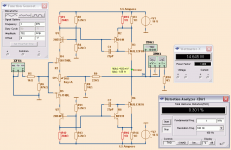
Here is my final try.
Changes from original Hiraga is in red.
- 2SC2911/2SA1209 are most suitable.
- Also added two 100 Ohm resistors for lower distortion.
- Along with those extra 1 Ohm resistors in output.
- Two 22p caps can be added for compensation.
- Bias is 1.87A. This means large heatsink
As can be seen we can get something like 21 Watt into 4 Ohm
This is not bad compared to original 5-6 Watt into 8 Ohm.
Attachments
I forgot to say that to get like 2 x 16 VDC
we need one transformer 2x12VAC and rectifier diodes/bridge
we need one transformer 2x12VAC and rectifier diodes/bridge
Dear Lineup,
That is absolutely wonderful thank you very much indeed.
I think this will become the solid state amplifier for the Mark Audio range of speakers.
I have nearly finished my FH3's, the Hiraga will be my next project. It will take me a couple of months to get it all together but as soon as I do I will report straight back here.
My warmest wishes to you - Jim
Hi, lineup,
May I suggest a larger transformer, as 12 V will get 15,7 no current (16,9-0,6-0,6) but any load will drop that significantly; with CRC filtering I suggest at least 2x16 volt (measured across a 5 ohm load). That's how I do it.
I like your developments of the original schema very much. The new drivers have a very very low Cob. The 'old' output pairs are a bit weak. Would be interested as to hear the effect on the sound stage.
albert
Lineup -
I've been working with this schematic for the last few weeks and I intend to build a monster for driving 8 ohm loads in the next few weeks (transistors are arriving soon). Can you tell me why you decreased the emitter resistors in the output stage to 0.5 ohm when using 16V rails? I like the idea of getting (a little) more power out of the amp, but I don't want to run a bias of nearly 2 amps.
Others -
I bought some of the parts (output transistors, mostly) from MCM Electronics. It sounds like these certainly aren't the originals -- does anyone have experience with them working well anyway? I bought the JFET's and the cascode BJT's on Ebay.
(I don't see an option to edit my post..)
Update:
I now see that the 0.5 ohm resistance increases the bias current in the output stage which is needed when driving a 4 ohm load to keep the amp in class A. So if I am to build this amp with 16v rails I should be able to still use 1 ohm emitter resistors with a bias of 800ma - 1000ma. Do people usually use pots for R1,R12 so that the bias is adjustable?
- Do people usually use pots for R1,R12 so that the bias is adjustable?
This is a good idea: Hiraga describes the amplifier as consisting of two halves.
The Hfe of the two sides never match perfectly. So adjusting the DC will also affect the amplification.
I observed that there is a slight preference for either the top side or bottom side to hit the power rail first when driven to almost full output. The difference is less than 100 mV RMS difference (seen on the scope) between sides in my implementation. A variable pot on R1/R12 would probably overcome this small inconvenience. In my Le Classe A I have done that, in an experiment.
I do have a distortion analyzer that allows me to see the effects.
Finding the right value though (this is implementation, not simulation) is going to take a long time I think as it involves iterations. I see it at this moment as just cosmetic though.
albert
Hello jarinal !
Glad to hear that you like monster sound. Nice and big amp you built !
Congratulations!
Glad to hear that you like monster sound. Nice and big amp you built !
Congratulations!
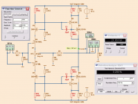
This is for 2x16 Volt operation.(I don't see an option to edit my post..)
Update:
I now see that the 0.5 ohm resistance increases the bias current in the output stage which is needed when driving a 4 ohm load to keep the amp in class A. So if I am to build this amp with 16v rails I should be able to still use 1 ohm emitter resistors with a bias of 800ma - 1000ma. Do people usually use pots for R1,R12 so that the bias is adjustable?
For 4 Ohm I recommend 0.5 Ohm and 1.5 Ampere.
For 8 Ohm operation you need not the extra 1 Ohm resistors.
And you set bias to like 1.0-1.1 Ampere.
These figures is for pressing the amplifier max possible output.
Of course you can chose to run smooth on less current.
Good evening gentlemen.
I Thought I'd share a few pictures of my own build.
An externally hosted image should be here but it was not working when we last tested it.
Bildr.no
Here are the intestines of my monster. The power supply is as simple as it gets. Just two 220 000uF capacitors, a rectifier i found on the dump and a 300VA toroid. I'm currently working on making the transformer shield fit. The ground routes got a bit messy while trying to reduce the power supply noise, but it's nearly dead silent now.
An externally hosted image should be here but it was not working when we last tested it.
Bildr.no
The case is a bigger version of osscar's. The cooling is a bit over dimensioned, as the amplifier rarely gets hotter than 30-40 Celsius with a bias of 700mA
The main reason for the big case are the two capacitors.
I must say I'm impressed by the sound. The bass is so unbelievably tight. My NAD T744 doesn't have nearly as good sound.
glad you have the nice monstre sound 🙂 excellent job
It is stable without caps.lineup,
that´s a very nice modification in post #767. Hopefully, the capacitor can be avoided.
For a prefect AC curve, use caps.
If only you knew just how devastating they are for the "AC curve", you probably would not say so.
- Home
- Amplifiers
- Solid State
- Hiraga "Le Monstre"