That's all I could find, dude...take it up with the author..
What you posted is the primary side of the transformer, what shows up at the line cord. The paper I linked to was full bridge on ac line, I described the depiction as that on the bridge side of the xfmr...
What the heck is that spike, leakage inductance?
Hey, have a great weekend..I'm outta here...
Cheers, John
Maybe there was a reason I went looking for DC on an AC line!
I've not used the system as an excuse. What I've pointed out is that there are elements of the system which are not considered by the designers, and it is those considerations which cause the system to be sensitive to the IC's.
It is not "sub optimal" IC design. It is the overall system. In addition, I have also layed the groundwork which show that the LINE CORD does indeed couple to the ground loop and affect it's role on return currents. Both by ground connection resistance, and by cord geometry.edit: Once it is understood that the line cord can indeed couple to the ground loop, several messy things pop their ugly head...haversine spectra is impacted by the diode reverse recovery speed, main supply storage capacitance, capacitor ESR, internal AC line layout, main supply wiring layout...man, it gets ugly. That is why I pointed out odd harmonics in the primary loop, even harmonics in the secondaries...so that others could measure and attribute.
Cheers, John
See your point John and I do agree. It`s so long since I learned how to avoid ground-loops that I forget to even concider it as a problem, but this can be a bit different in other countries w. different net.
As you say, many designers do not do this too good, so we need to know our latin well enough to pick the good ones. Or diy, modify..
Anyway, even if grounding is done the right way you`ll still hear IC`s. Allmost all conductors degrades sound more or less, I`ve only found one who doesn`t.
Anyway, even if grounding is done the right way you`ll still hear IC`s.
How would you know that the grounding is done right? Unless you've designed and fabricated the actual equipment to eliminate loop coupling, you have no control nor idea how the current will travel. As I pointed out, the line cords and IC seem to be the most obvious areas for ground loop problems, but it is also a concern within the equipment. Using just a star grounding technique certainly does not guarantee perfection.
Allmost all conductors degrades sound more or less, I`ve only found one who doesn`t.
From your statement, I would believe that your equipment is not impervious to external loops.
As I see it, the most pressing issue is the understanding that the problem exists. Once that is understood, all the "injuneers" involved can quickly figure out how to test for it...then redesigning to eliminate it is trivially easy..
Unfortunately, this avenue of research could severly impact high end wire and equipment manufacturers. It is not my end goal to achieve this.
Cheers, John
High,
Maybe I could contribute with some illustration here?
Some time ago I have stumbled on this same effect, while trying to illustrate to my collegaues (physicists..) the need to terminate well their link to a detector.
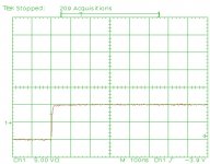
The first shot is a 10V step signal from a 50ohm signal generator into a terminated 50ohm line. The rise time - dominated by the generator - is ~5nsec.
So this is the "intrinsic" speed of the system.
Maybe I could contribute with some illustration here?
Some time ago I have stumbled on this same effect, while trying to illustrate to my collegaues (physicists..) the need to terminate well their link to a detector.
The first shot is a 10V step signal from a 50ohm signal generator into a terminated 50ohm line. The rise time - dominated by the generator - is ~5nsec.
So this is the "intrinsic" speed of the system.
Attachments
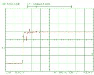
The oscilloscope is showing what is going on at the receiving end. If I lift the termination there, that is the new configuration is:
generator -50ohm back term. - 50ohm line - 1Mohm osc., that is, at the receiving end there is full reflection of the incident wave, then we will see 10V incidental step +10V reflected wave = 20 V step as a net result on the screen.
Plus some reflections coming back from the not fully perfect termination at the generator. The rise time is still less then 10nsec.
Attachments
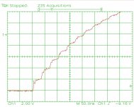
The 50ohm line is ~3m long which equals to 16nsec propagation delay. Full trip is 32nsec.
The generator produces the 20V step into the following series system: it's own 50ohm series back termination, the 820ohm resistor, the 50ohm line impedance.
The net current flow is: ~22mA.
Up to now everything is real, resistive, so at the 50ohm line we will see an instant 22mA*50ohm = 1.08 V incident wave step.
Like before, this ~1V incident wave at the other, unterminated end (shown by the scope) will show up like incident + fully reflected wave, that is, a 2V step.
Now this reflected 1V step is traveling back on the line, and gets reflected on the ~almost open (870ohm), transmitter side, and everything restarts again.
This is the mechanism which gives those 2V steps mounting always higher, at each 32nsec periods. Obviously, the initial clear steps are getting "dissolved" later, by the cable losses, by the termination losses, so the height of the steps are decreasing with time.

You can see at the start the waveform looks just like the #925 one, except smaller magnitude due to the 870/50 mismatch. Each full bounce increases the amplitude, but by less each time as some signal gets lost in the back termination.
Alternatively, calculate the capacitance of the cable. Then calculate an exponential rise from a CR formed by that and 870R. The result should roughly follow the last picture, but smoothly without the steps.
Alternatively, calculate the capacitance of the cable. Then calculate an exponential rise from a CR formed by that and 870R. The result should roughly follow the last picture, but smoothly without the steps.
I think this setup, a ~1kohm output resistance at the generator end, + a very high, practically open (50-100kohm) input impedance at the receiver end is a quite common, almost standard "tube like" system configuration..
Also, think of the power stage configuration: It's true that at DC the output impedance is very low, but it rises fast either because of negative feedback, or, with tubes, the output transformer leakage inductance.
The receiver end is badly terminated because of the speaker inductance, at high frequencies. The line impedance is even lower, so nice mismatch is guaranteed.
And yes, DF96, it can be looked upon both ways: lumped element approach or this, t line approach - as You cleared it up with John.
The receiver end is badly terminated because of the speaker inductance, at high frequencies. The line impedance is even lower, so nice mismatch is guaranteed.
And yes, DF96, it can be looked upon both ways: lumped element approach or this, t line approach - as You cleared it up with John.
This is the mechanism which gives those 2V steps mounting always higher, at each 32nsec periods. Obviously, the initial clear steps are getting "dissolved" later, by the cable losses, by the termination losses, so the height of the steps are decreasing with time.
The step height is a result of the reflected amplitude. As the wave bounces back and forth, the reflection coefficient will determine how large each step will be. If the reflection coefficient at the load is -.9 and the source is -1, the first bounce will be 90% of the signal, the second 81%, third 72.9 etc. Yes, cable r and losses will also come into play, but for audio stuff, I'd not consider those at first run.
Alternatively, calculate the capacitance of the cable. Then calculate an exponential rise from a CR formed by that and 870R. The result should roughly follow the last picture, but smoothly without the steps.
Yes. For the setup he has described with the 870 resistor, the cable capacitance will dominate the line so a simple RC calc will suffice.
Cheers, John
Also, think of the power stage configuration: It's true that at DC the output impedance is very low, but it rises fast either because of negative feedback, or, with tubes, the output transformer leakage inductance.
The receiver end is badly terminated because of the speaker inductance, at high frequencies. The line impedance is even lower, so nice mismatch is guaranteed.
And yes, DF96, it can be looked upon both ways: lumped element approach or this, t line approach - as You cleared it up with John.
Actually, not exactly. For the example you gave with the 820 ohm series resistance at the generator, there is indeed 22 mA available to charge the line, so a simple RC is essentially good to go.
For a speaker on the other end and a zero impedance source, the simple RC will be inaccurate. When the system has settled down, the load defines the current and the voltage in the line. Not the generator impedance.
The only way to model the system with good accuracy is to break the t-line into many RLC elements. If for example, you use only 1 R, 1 L, and 1 C, you get one result. Use 2, it changes. Use 100, you get much closer to what a t-line will do. But most importantly, you build into the model the line current, line inductance, and line energy storage. I stress the inductance part only because a low value load forces the line to have far more inductive storage than capacitive.
I also use the t-line model to easily include the physical dimension of the line.
These are the exact same issues one wrestles with for a pulse forming network for a kicker magnet. Many discrete L's and C's vs 4 coaxial lines running 100 feet or so. At least with the L/C strings, you can tailor the network somewhat, whereas coax cables incur a droop due to cable resistance..at 3 kiloamps, droop is a big penalty to pay for simplicity.
Cheers, John
Last edited:
PaleRider said:Anyway, even if grounding is done the right way you`ll still hear IC`s.
How would you know that the grounding is done right? Unless you've designed and fabricated the actual equipment to eliminate loop coupling, you have no control nor idea how the current will travel. As I pointed out, the line cords and IC seem to be the most obvious areas for ground loop problems, but it is also a concern within the equipment. Using just a star grounding technique certainly does not guarantee perfection.
Almost all conductors degrades sound more or less, I've only found one who doesn't.
As Ive mentioned; I stumbled over a simple diy-IC years ago that just performs flawless on all kind of equipment, good ground-circuits or not. So the problem is not just internal, it's about how to make a IC too.From your statement, I would believe that your equipment is not impervious to external loops.
As I see it, the most pressing issue is the understanding that the problem exists. Once that is understood, all the "injuneers" involved can quickly figure out how to test for it...then redesigning to eliminate it is trivially easy..
Unfortunately, this avenue of research could severely impact high end wire and equipment manufacturers. It is not my end goal to achieve this.
Until this day I haven`t heard any other come up with a flawless unaudible IC, only theories.
You still haven't told us what this IC consists of, or in what sense it is "flawless". Presumably you have measurements showing the difference in signal from it and a normal 'flawed' cable? And on several different items of equipment? Or do we just have to trust your ears, when many of us don't even fully trust our own ears?
I seem to have lost track. Are we still talking about analog audio interconnects and speaker cables? Both of which have bandwidth limited signals or are we talking about signals from an audio point of view that are almost step functions?
I seem to have lost track. Are we still talking about analog audio interconnects and speaker cables? Both of which have bandwidth limited signals or are we talking about signals from an audio point of view that are almost step functions?
An excellent question.
I use an infinitely fast step function. This allows a clean understanding and testing of the system response. As you point out, this is certainly not what occurs in an audio system.
However, using the infinitely fast step in any analysis will provide an ideal settling time. That settling time using such a waveform will give the absolute fastest response the system is capable of with ideal components. Once we start to introduce reality in the form of components and signals, the system response can only slow down....never speed up.
So if the "high speed" system response is 10 uSec for example when the load is mismatched to the cable by a ratio of 100 or so, reality will be even slower. How much slower is unknown given the real components we must use.
It's just a tool to provide level of effect. If it produced pico or nano level times, then it is not necessary to proceed any further.
Cheers, John
found these on line
http://www.dynaudio.com/eng/pdf/DYN_Ocos_TechnGrundl_INT.pdf
also googled "ocos the formula"
http://www.dynaudio.com/eng/pdf/DYN_Ocos_TechnGrundl_INT.pdf
also googled "ocos the formula"
An excellent question.
I use an infinitely fast step function. This allows a clean understanding and testing of the system response. As you point out, this is certainly not what occurs in an audio system.
However, using the infinitely fast step in any analysis will provide an ideal settling time. That settling time using such a waveform will give the absolute fastest response the system is capable of with ideal components. Once we start to introduce reality in the form of components and signals, the system response can only slow down....never speed up.
So if the "high speed" system response is 10 uSec for example when the load is mismatched to the cable by a ratio of 100 or so, reality will be even slower. How much slower is unknown given the real components we must use.
It's just a tool to provide level of effect. If it produced pico or nano level times, then it is not necessary to proceed any further.
Cheers, John
Isn't this similar to the test that "Shunyata" used on their power cables?
Isn't this similar to the test that "Shunyata" used on their power cables?
If I remember correctly, they were testing the stiffness of the cords to a step stimulus, so it's kinda like it.
My biggest concern with their test was, it did not include the romex to the load panel. So, no matter how stiff the cord was, it's tied to the utility with a long length of spagetti.
Cheers, John
- Status
- Not open for further replies.
- Home
- Design & Build
- Parts
- Interconnect cables! Lies and myths!