Very nice guitar amp - not sure why you needed two ?
, it is not mine to keep though.
Good to hear you have the wrinkles ironed out. What will you use as a case?
Member
Joined 2009
Paid Member
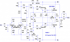
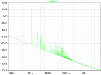
This isn't my amp. I offered the TGM2 modules to a friend, who supplied the heatsink for me to attach them to. The modules were no longer being used since my HT set up was only using 3 already built channels in my DIY unit and there aren't any other projects to use them for since I'd like to try something new. However, I thought it would interesting to try them out on the higher rail voltages which I've not done before, so I decided to donate some time to it. I've attached the as-built schematic and simulated fft when dissipating 50W into a 8 Ohm resistive load.
I plan to turn my attention to the follow-on of my TGM3; I may call it TGM4 (original huh?) since I plan to evolve it and make a new pcb for it to take advantage of what I've learned.
I plan to turn my attention to the follow-on of my TGM3; I may call it TGM4 (original huh?) since I plan to evolve it and make a new pcb for it to take advantage of what I've learned.
Attachments
Last edited:
tgm2.9
the base stoppers look enormous.
C8 10pF could do with a series resistor. Maybe a 50k pot to tune in the effect.
the base stoppers look enormous.
C8 10pF could do with a series resistor. Maybe a 50k pot to tune in the effect.
Member
Joined 2009
Paid Member
There is no C10 on the latest schematic ? do you mean the phase lead comp cap ? - if so, I had thought about that, but no provision on the pcb. This is a 'finished' design, but any suggestions for improvement will be filed for my next project and are much appreciated !
Member
Joined 2009
Paid Member
Well the module has been installed into chasis and powered up - all seems to work fine.
Unless there are some future tweaks and mods to improve it, this likely marks the end of the TGM2 file.....
Unless there are some future tweaks and mods to improve it, this likely marks the end of the TGM2 file.....
Member
Joined 2009
Paid Member
The amp went off to another hobbyist - the learning I wanted has been achieved. Sound impressions being obtained, but so far they seem to mirror my own observations. Clean sound, but treble can be too honest. Some tweaks are still left to be explored, adjustments to compensation, upgrade of VAS devices from BD139 to something with lower Cob.
Next....trying to narrow down the choices for future projects so as not to overload my small brain - no more LTPs, I've decided I don't like them in principle or in practice. No CCS's either, don't like them in principle either, and by implication there will be no current mirrors.
I've been looking at TGM3 design again now that the dc offset problem was fixed securely. I may update it and rebuild my home theatre amp from scratch using this design, it has pretty much everything that I like about a gnf amplifier and the sound suits my taste more than TGM1 & 2.
Last edited:
no more LTPs, I've decided I don't like them in principle or in practice. No CCS's either, don't like them in principle either, and by implication there will be no current mirrors.
Sounds inspired. 🙂
If no LTP, have a look at the input stage I'm trying for my latest (and greatest) guitar preamp: http://www.diyaudio.com/forums/solid-state/182911-guitar-pre-clean-some-sizzle.html#post2464979
Could be a worthwhile starting point.
Member
Joined 2009
Paid Member
I like your design, I like it a lot, CFP input with JFET. 'Twas an earlier idea in one of the TGM threads and thoroughly endorsed by Mumba !
I'd consider using a JFET somewhere in the future - where did you get yours from ?
I'd consider using a JFET somewhere in the future - where did you get yours from ?
Why put a series resistor with C8? What is the effect that is tuned?
Very nice Bigun.
1u for L1 is large. I found in simulation that sometimes as low as 200nH was enough (determined by hanging a very large capacitor off the output, with and without various values of inductance). Also, C11 in most cases can be 10nF (maybe higher if R22 is inductive?). Both of these changes will help HF I think.
- keantoken
Hi,
any exorcist would affirm that curses do exist, for instance, have you heard about the phase lead curse?
any exorcist would affirm that curses do exist, for instance, have you heard about the phase lead curse?
A de-Qing resistor in series with the phase-lag could, depending on the situation, improve stability. That is what I think. I am curious to swap notes with Andrew.
- keantoken
- keantoken
Member
Joined 2009
Paid Member
Hi Keantoken,
I'm afraid I guessed at the value of the output inductor based on what others have claimed for their home-made inductors. What I did notice though, was that there was always a bit of ringing on the square wave test with sufficient levels of capacitance at the output and even gobs of Cdom didn't eliminate it - of course an ultra-fast square wave is a brutal thing too. I didn't try a series resistor with the phase lead cap but that makes perfect sense to try.
The zobel (C11) was adopted from TGM1, which at the time was based on information I could find from similar designs such as AKSA, DX etc. rather than from a proper understanding of it's function.
Member
Joined 2009
Paid Member
Hi,
any exorcist would affirm that curses do exist, for instance, have you heard about the phase lead curse?
Phase lead curse, well that's a novel thing indeed !
Anyway, I feel a little more knowledgeable about amplifiers after this messing around with TGM2 again.
1u for L1 is large. I found in simulation that sometimes as low as...
That would be the key phrase: "I found in simulation...".
In actuality, 1uH is low.
I'd consider using a JFET somewhere in the future - where did you get yours from ?
The jfet or the idea? The fet came from Digikey, the idea came from an RF amplifier that I adapted. Low noise, high input impedance. A fair chunk of distortion for the stage though (but that don't bother us 😀 ).
Member
Joined 2009
Paid Member
A fair chunk of distortion for the stage though (but that don't bother us 😀 ).

Well my word is not always right, you should ascertain the facts for sure in your own studies. Each amplifier has it's own appropriate network. Symasym used 500nH. It is very possible to determine what is the best output zobel empirically. IMO, these things can only be determined for certain using a real prototype.
Bigun, if you connect a capacitor directly to the output, your load effectively becomes a resonator (whether with the output zobel or simply the inherent inductance produced by the feedback mechanism of the amp). With a finite output impedance, some ringing cannot be avoided. That is, unless your amp has such high output impedance that the RC filter formed by the cap absorbs the frequencies which excite the resonance. And then you'd see a stable square wave, but, is it really better, or just different?
Up to a point, adding more compensation only serves to turn the amp into a crude lowpass filter. If at this point the amp is still not stable, it means you have an internal resonance and a new type of compensation must be added or the current compensation reworked. This is where a lot of people give up and deem the design "unworkable". Compensation is not simply something you do after the fact to complete a design - it is its own science. Perseverance pays off.
- keantoken
There is some math involved for the optimum value of the output inductor but it escapes me. AndrewT knows it (I'm sure). It has little to do with the compensation of the amp itself.
Self recommends between 1 to 7uH in his book and advises that all high feedback amps should have one, to guard against capacitive loads.
Self recommends between 1 to 7uH in his book and advises that all high feedback amps should have one, to guard against capacitive loads.
- Status
- Not open for further replies.
- Home
- Amplifiers
- Solid State
- TGM2 amplifier