Member
Joined 2009
Paid Member
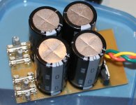
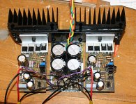
PSU is 'finished', ready to have output wires soldered in.
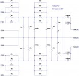
Here's the as-built final schematic. Produces 42V at no-load, takes a few minutes for the bleeder resistors to discharge the caps.
Soft recover diodes, 50V caps.
100R in parallel with 5A fuses helps keep the rails up if a fuse is lost and allows no-load preliminary test of amp by connecting with fuses removed.
Attachments
Sweet! You don't have any high frequency bypass caps after the rectifiers though. A small issue that can be fixed if needed by tacking them on on the board bottom. 100nF ...(dirty word warning!!)...ceramic.
😀
😀
Member
Joined 2009
Paid Member
Good idea. In fact, the high freq bypass on the last pair of caps are also ceramic - nice Japanese one's from an old Yamaha receiver. I'm less worried about Ceramic in the PSU but more nervous of using them for something like Cdom.
Actually, quite a few of the bits are tacked on the bottom.
Actually, quite a few of the bits are tacked on the bottom.
Attachments
Member
Joined 2009
Paid Member
I'd be interested in some ideas and thoughts from the forum on this next step in the process.
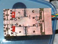
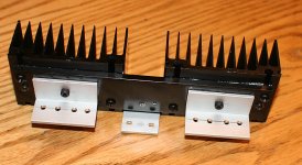
I've got a heatsink now, pulled out of an old chasis. The two TGM2 amplifier boards and the new power supply all need to be mounted to the heatsink so that I end up with a simple 'module' to install back into the chasis.
I was thinking of a simple 'L' bracket.
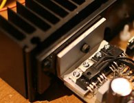
But I'm toying with the idea of reusing the big power transistors still stuck to the heatsink. I'd have to mount the pcb's to the heatsink with a small bracket and then fly wire the power devices to the existing pcb's after first removing the existing TO-220 power devices.
The benefit is a better thermal design for the power output devices - very attractive proposition. As you can see from the photo, the fly-wires could be short but not zero length. Although I've seen other amplifiers use off-board power devices I'd be interested to know from those of you with the relevant experience how much trouble I might be getting myself into if I go that route ?
I've got a heatsink now, pulled out of an old chasis. The two TGM2 amplifier boards and the new power supply all need to be mounted to the heatsink so that I end up with a simple 'module' to install back into the chasis.
I was thinking of a simple 'L' bracket.
But I'm toying with the idea of reusing the big power transistors still stuck to the heatsink. I'd have to mount the pcb's to the heatsink with a small bracket and then fly wire the power devices to the existing pcb's after first removing the existing TO-220 power devices.
The benefit is a better thermal design for the power output devices - very attractive proposition. As you can see from the photo, the fly-wires could be short but not zero length. Although I've seen other amplifiers use off-board power devices I'd be interested to know from those of you with the relevant experience how much trouble I might be getting myself into if I go that route ?
Attachments
Member
Joined 2009
Paid Member
Member
Joined 2009
Paid Member
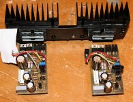
I've attached the pcb's to the L brackets and installed the wiring. A flap of anti-static bag was cut and attached underneath the power supply pcb to ensure adequate isolation from the floor of the chasis.
The LTP tail resistors have been increased from 6k8 to 8k2 to allow for the higher rail voltage.
I'll wheel in a bench top supply with a current-limit to test it out before I plug it in.
The LTP tail resistors have been increased from 6k8 to 8k2 to allow for the higher rail voltage.
I'll wheel in a bench top supply with a current-limit to test it out before I plug it in.
Attachments

Lookin good! 
Did you test the power supply board?
There are a lot of junctions before the heat from the output reach the heatsink, did you put thermal grease at each join?
BTW, what happened to your idea in post #204, to use the larger devices already attached to the heatsink? What were these anyway?
Did you test the power supply board?
There are a lot of junctions before the heat from the output reach the heatsink, did you put thermal grease at each join?
BTW, what happened to your idea in post #204, to use the larger devices already attached to the heatsink? What were these anyway?
Member
Joined 2009
Paid Member
Hi John,
Thanks for taking a peek... yep I've tested the psu to the extent of measuring the voltage under load (haven't put a CRO on it yet) and found that the SMD resistors in the rails, between capacitors, were dropping too many volts so I strapped them with a good olde fashioned thru-hole 0R33. Otherwise seems good.
I don't have any thermal grease - I've used something my work colleagues call 'gap pad'. It comes in sheets, feels like rubber. To use it you cut a piece out the size you want and peel off the plastic from both sides. Put it between the two parts you want to thermally couple and then bolt them together. The stuff squishes out between the two parts. Not yet sure I'm going to be happy with the large thermal distance between the Vbe multiplier and the output devices - the Vbe multipliers are bolted directly to the heatsink rather than the same bracket the output devices are bolted to. I may end up looking to glue the Vbe multiplier directly to an output device.
I didn't see a solid way to mount the pcb's to the heatsink without a bracket and not having metal in my junk box I was ultimately at the mercy of what I could find at Home Despot, so I abandoned using the existing parts. I don't know the history of the original parts - they are the same as what you used on Patchwork.
Ah, that isolation material should be good. I have thermal grease but stopped using it in favour of a wax/silicone based lube in a stick form. It is what I used (along with mica washers) in my 6 channel Patchwork and that has been running for nearly 2 years without a problem. Any future projects will be the stick lube and a thin layer of water based urethane on the device itself for electrical isolation.
The vbe multiplier may be fine where it is, depending on the idle current you'll run and the case configuration. Still, given that they are on flying leads, you can easily get them closer to the outputs. If that gap pad is adhesive, maybe use it to glue them down. At least you have a chance of cutting them free if you want to change something, unlike epoxy.
The vbe multiplier may be fine where it is, depending on the idle current you'll run and the case configuration. Still, given that they are on flying leads, you can easily get them closer to the outputs. If that gap pad is adhesive, maybe use it to glue them down. At least you have a chance of cutting them free if you want to change something, unlike epoxy.
Member
Joined 2009
Paid Member
Member
Joined 2009
Paid Member
I put a scope on the power rail at regular idle current. Get around 30mV pk-pk of ripple. The ripple doesn't appear to have any nasty h.f. content so the CRC is doing it's job.
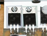
I've used Silicone to glue the Vbe multiplier onto the output power devices. Wow, MUCH better bias stability - rock solid now, although not tested into a dummy load yet.
I've used Silicone to glue the Vbe multiplier onto the output power devices. Wow, MUCH better bias stability - rock solid now, although not tested into a dummy load yet.
Attachments
Gareth,
If you fail to tighten down a single output device, it will quickly heat more than others and hog the current, particularly with a small Re, rapidly entering thermal breakdown. The equivalent with an auto engine is tightening the big end bolts (or is that Bigun bolts?) to the precise specified torque.
BTW, sharp transitions on ripple are equivalent to HF by Fourier analysis. The key is probably to have really good PSRR.
Hugh
Member
Joined 2009
Paid Member
Hugh,
Thanks for the advice - I'm sure you recognize some of your inspiration in this design.
Yes, I found that I was looking for the hottest device and then tightening the screws, going on until all the devices were well behaved. But, with the Vbe multiplier on the main heatsink there was just too much distance between it and the power devices and no amount of screw tightening would make it stable enough in my opinion.
I did have the joy of experiencing full thermal runaway, once on this project and once with an old Ford - cracked the cylinder head!
Member
Joined 2009
Paid Member
Member
Joined 2009
Paid Member
Also installed the phase lead compensation caps. I tried about 1pF of 'gimmick' teflon caps but this produced ringing on a 1kHz square wave. I increased it to 10pF.
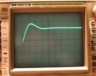
I'm not a big fan of square wave tests, I figure the rising edge of the input waveform, if steep enough, will produce all sorts of nasties regardless of whether the amplifier has a clean bill of health. Nevertheless I'm happy with 10pF, producing a little overshoot.
I took some scope photos.
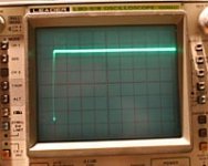
First one is input signal rising edge, which measures at 100ns or less - yikes.
Second one is the output rising edge at 10us/Div, you can see the little overshoot
Third one zooms in the overshoot at 1us/Div. The rise time to the peak of the overshoot is around a microsecond and it's damped out pretty quickly.
The output square wave was otherwise flat and symmetrical.
I used an 8 Ohm dummy load, made up from power resistors paralleled up and bolted to a heatsink. I need not have worried about the heatsink - the output devices of the amplifier got pretty hot after a couple of minutes so I didn't leave the square wave input in place long enough to heat up the load.
I'm not a big fan of square wave tests, I figure the rising edge of the input waveform, if steep enough, will produce all sorts of nasties regardless of whether the amplifier has a clean bill of health. Nevertheless I'm happy with 10pF, producing a little overshoot.
I took some scope photos.
First one is input signal rising edge, which measures at 100ns or less - yikes.
Second one is the output rising edge at 10us/Div, you can see the little overshoot
Third one zooms in the overshoot at 1us/Div. The rise time to the peak of the overshoot is around a microsecond and it's damped out pretty quickly.
The output square wave was otherwise flat and symmetrical.
I used an 8 Ohm dummy load, made up from power resistors paralleled up and bolted to a heatsink. I need not have worried about the heatsink - the output devices of the amplifier got pretty hot after a couple of minutes so I didn't leave the square wave input in place long enough to heat up the load.
Attachments
I'm not a big fan of square wave tests, I figure the rising edge of the input waveform, if steep enough, will produce all sorts of nasties regardless of whether the amplifier has a clean bill of health. Nevertheless I'm happy with 10pF, producing a little overshoot.
I would not put an amp into action without doing a whole bunch of square wave tests. Square waves will show all the good stuff. 🙂
That overshoot is a sign of under-compensation. Maybe not enough to cause instability but fortunately, you can check this before you button everything up. With your output inductor in place, put a capacitive load on the output (in parallel with the dummy load). Start off small and work your way up in uF to see if your amp goes crazy. As you know, many speakers have crossovers with caps and inductors, so it's a good idea to make sure the amp is stable with these loads.
Speaking of inductors, did you put a Zobel on the output? This guards against inductive loads. Another test, similar to the cap test, is to drive an inductive load and see if the amp goes haywire. Use a sine wave for these tests at different frequencies. If it passes these tests at high frequency (>10khz) then your amp is stable.
Member
Joined 2009
Paid Member
Thanks John, I'll find time this weekend to do that. I've never taken my amps to this level yet since my HT is not as demanding as hi-fi.
Yes, I do have a zobel on all my amps, before the output inductor.
The compensation is 68pF. Now, without giving too much away, the commercial design (I think you know which one) that inspired this amplifier uses less compensation than this so I have some confidence that I'm not too light.
I decided it was time to listen to it, I was getting bored. I hooked it up to my PMC floorstanders via some very large caps as 'cheap protection'. The amp is a power amp - no volume control. The only source I have with volume control is my ipod.
It sounded awful. Sibilance for starters. I suspected it was because of the MP3 recording quality. I re-recorded a CD using Apple Lossless and now it sounds just fine - phew !
The wife caught me playing by myself in the basement (!) - says it sounds great.
I'm going to let it run for awhile to warm up the heatsinks properly and check the bias.
The wife caught me playing by myself in the basement (!)
Yeah, that happened to me a couple times too.
🙂
Compensation is going to be an individual thing and you can't base it on how a similar amp performes. What's more, as soon as you put the amp in an enclosure, you may need to adjust the compensation again. I know I have.
Hugh can verify this, I'm sure.
Hugh can verify this, I'm sure.
Member
Joined 2009
Paid Member
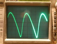
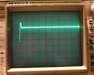
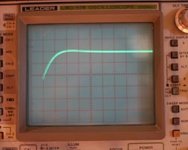
I put 10nF and 100nF across the output as a load, in parallel with 8R. By upping phase lead to 22pF I can get a nice rising edge - no ringing or overshoot. By 470nF things weren't good and that was as far as I wanted to push it.
I won't be adjust the phase lead compensation any further, if it needs more I'll turn attention to Cdom. Right now 68pF for Cdom sounds good, not tizzy.
[The scope images shows the rising edge. Timebase at 1uS per DIV, so we're looking at a rise time of 2uS. The zero level is at the centreline so the vertical height is very compressed whilst the horizontal time axis is very stretched and we're only seeing the first few uS of the square wave itself.]
Attachments
Last edited:
- Status
- Not open for further replies.
- Home
- Amplifiers
- Solid State
- TGM2 amplifier