Member
Joined 2009
Paid Member
I took an empirical approach, following the method that seems popular - winding some really thick wire around a power resistor (only I used a hex key as a former for the winding so I could get a longer coil out of it).
I can see how a resonator would be formed from the L-C. It's possible I've set Cdom too high as a result of trying to keep the square wave under better control, but the opportunity remains to do some listening tests on some values a little lower and higher to optimize it.
A problem with determining final values by trial and error is that you need to test it with a wide range of speakers and cables which I'm not set up to do.
I have a few commercial output inductors in an old HT amplifier somebody donated to my junk pile - they look fairly substantial so I may use these in a future amp build.
I copied Cherry's recommendation into a spreadsheet. The speadsheet followed Dr Cherry precisely and allowed for the stabilising cap before or after the L//R, just as Thiele had originally suggested.AndrewT knows it
Since then I have experimented with the Pi version of the Thiele Network and now find that the Network does not need much alteration (if any) to suit the speakers/load.
I took an empirical approach, following the method that seems popular - winding some really thick wire around a power resistor
I have a few commercial output inductors in an old HT amplifier somebody donated to my junk pile - they look fairly substantial so I may use these in a future amp build.
Yes, this is probably the most accurate way to do it without measuring. A uH more or less will not make much of a difference, I think.
Supposedly, the air core inductor (found on most commercial designs I've taken apart) are superior to the winding around the parallel resistor method.
Member
Joined 2009
Paid Member
I'm planning to rebuilt my home theatre amp and will re-use these commercial coils as-is. I like the approach you took with your 6-channel amp in that it's been designed to be good enough for hi-fi (in your case tri-amp) not just home theatre so I'll be looking into more of these details.
To have a second opinion, I looked through Cordell's book.
He says L/R networks typically range from 500nH-5uH, 1R-10R. After having time to reflect, 500nH did seem to be the basic minimum for a BJT output amplifier. I was playing with the idea of making a high-performance headphone amplifier, using a Zobel to help stabilize it, which is why I recall experimenting with values below 500nH (but on that note, for a headphone amp the parallel R increases to about 33R and upwards).
I think that if you had a fast enough, well-behaved amp, the trace inductance from output to binding post would be enough to keep it in check, as long as you avoid highly reactive cables. I think this is the philosophy behind the super-high slew rate amps. Wouldn't be an easy design though.
To eliminate EM interaction, I wonder about toroidal air core inductors? Or maybe even a bismuth toroid, so that more turns could be used, producing a more uniformly toroidal magnetic field?
- keantoken
I think that if you had a fast enough, well-behaved amp, the trace inductance from output to binding post would be enough to keep it in check, as long as you avoid highly reactive cables. I think this is the philosophy behind the super-high slew rate amps. Wouldn't be an easy design though.
If my understanding is correct, the output inductor shouldn't have any effect on slew rate.
Also, there is the idea that an amp may sound better without the inductor, so it should be avoided at all cost. This is unsubstantiated and from where I sit, it is better to have an amp that is minimally effected by output load as opposed to one that may Chernobyl if you use the wrong cables.
I'm planning to rebuilt my home theatre amp and will re-use these commercial coils as-is. I like the approach you took with your 6-channel amp in that it's been designed to be good enough for hi-fi (in your case tri-amp) not just home theatre so I'll be looking into more of these details.
I learned much on that project, especially with regard to grounding. Most of the stuff I learned has been augmented or outright disproved by my recent foray into the world of guitar amplification. This is a whole new can of worms and may actually be a better starting point for most of us aspiring amp designers. Issues I had no clue about become of paramount importance in high gain amplification.
On every project I learn a bit more but lately, it seems like my capacity for understanding this stuff has taken a leap. Things just click like they are obvious. I must be hitting my stride...🙂
Good luck with your project and I will be following the progress with anticipation. I hope I can help out (no, I won't cut up your idea anymore - it's time for 'good John' to return 🙂 )
Member
Joined 2009
Paid Member
Don't go and get nice on us, I need your input to keep me honest with these project !
I'd like to get started soon, but I have a lot of business travel coming up and won't be in a position to do much until April.
I'd like to get started soon, but I have a lot of business travel coming up and won't be in a position to do much until April.
Don't go and get nice on us, I need your input to keep me honest with these project !
😀
It's a pretty thin veneer actually, so I'm sure the ugliness will break through again...

I don't know exactly how reactive a cable can be. My understanding is that oscillation is caused by negative impedance interacting with time constants. A cable is passive, so it can't have negative impedance. So if the amp is designed properly, and has no negative impedance regions of it's own, then it should be stable into any cable.
I agree that an amplifier should be stable into any cable, and I wouldn't want to live meters away from an RF transmitter. Cordell talks of terminating speaker and interconnect cables to eliminate their transmission line properties, which can excite the instabilities of the amplifier.
I think using alternate compensation techniques, an amplifier can be made which is impervious to capacitive loading. With traditional Miller compensation, the output impedance goes to -180 degrees. This is negative impedance, no wonder why they always oscillate into caps. I don't think this kind of amplifier can be unconditionally stable unless it has either high output impedance (and/or low NFB), or a zobel.
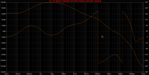
Just for intrigue I've attached the OLG of one of my latest experiments. Compensation is an open field, I think there is more to be "discovered" here.
- keantoken
I agree that an amplifier should be stable into any cable, and I wouldn't want to live meters away from an RF transmitter. Cordell talks of terminating speaker and interconnect cables to eliminate their transmission line properties, which can excite the instabilities of the amplifier.
I think using alternate compensation techniques, an amplifier can be made which is impervious to capacitive loading. With traditional Miller compensation, the output impedance goes to -180 degrees. This is negative impedance, no wonder why they always oscillate into caps. I don't think this kind of amplifier can be unconditionally stable unless it has either high output impedance (and/or low NFB), or a zobel.
Just for intrigue I've attached the OLG of one of my latest experiments. Compensation is an open field, I think there is more to be "discovered" here.
- keantoken
Attachments
Member
Joined 2009
Paid Member
I guess cables can have all sorts of evils depending on how they are made, terminated and how long they are. And then there's the speaker, it is a complex impedance device and that's not even allowing for the cross-over network if one is being used.
I was thinking that even a simple EF output by itself has significant local feedback via Re and this is the 'feedback loop' that becomes unstable depending on the load - which itself is part of the comp network for the EF local feedback loop since it's all hanging off the emitter.
I was thinking that even a simple EF output by itself has significant local feedback via Re and this is the 'feedback loop' that becomes unstable depending on the load - which itself is part of the comp network for the EF local feedback loop since it's all hanging off the emitter.
I don't know exactly how reactive a cable can be. My understanding is that oscillation is caused by negative impedance interacting with time constants.
Mr. Kean,
My understanding:
The kind of oscillation we need to avoid is parasitic and that is caused by positive feedback. When the output of a high feedback amp is loaded with a capacitance or inductance, the phase changes and if there is not enough margin, positive feedback results.
Is it possible we are describing the same mechanism from different perspectives?
Would you agree that if an amp has an output impedance that perfectly models real passive components, with phase shifts that never get over 90 degrees, that no passive component at it's output can cause it to oscillate, just like passive components themselves cannot oscillate without an active circuit attached? And that as such, it is the negative impedance component to an amplifier's output impedance that causes oscillation into certain loads?
This is assuming that the amp is already stable when not loaded. And if the amp's own feedback loop contained no negative impedance, would it be possible for it to oscillate?
- keantoken
You're losing me with the 'negative impedance' stuff.
Fact is, the output of a feedback amp is the source for the feedback. Putting a capacitance or an inductance on the output will cause phase shift and this extends to the feedback loop. Shift the phase enough, regardless of any other conditions, and positive feedback is the result. Oscillation.
Optimizing the phase margin (via frequency compensation) and trying to isolate the output from the load with the Zobel and output inductor reduce the likelihood of this happening...or so I've read.
Passive components cannot oscillate. If the feedback loop functioned with the same impedance characteristics of passive components, then it couldn't oscillate either, right?
So then it is something unique to active circuits which creates the possibility of oscillation. No matter the magnitude of the signal, there can be no oscillation without a phase shift exceeding 180 degrees. So positive feedback cannot cause oscillation unless there is a -180 degree phase characteristic. Imagine a resistor with an impedance flipped to -180 degrees. As voltage decreases, current would increase; negative impedance. Am I right?
I'm not saying you're wrong, and I don't think you are, but I think there is more to know.
- keantoken
Member
Joined 2009
Paid Member
I think we're in agreement that the kind of oscillations we're talking about here are related to circuits that do contain active elements so that some kind of amplification is going on which would be susceptible to oscillations if positive feedback were to happen.
The way I see it is that an EF has a 'local' feedback circuit at it's emitter (Re), which also happens to be the output - so the load which is attached to the emitter is automatically part of the feedback circuit and if this load produces enough phase shift such that we are in a +ve feedback situation we can get oscillations. The passive components don't oscillate by themselves, but they produce the phase shifts necessary to cause +ve feedback at the EF stage. The current/voltage through these passives will therefore have a time varying component and so the signal seen in the passives will be oscillating.
There's always more to know, but is it worth knowing ? (that's a bit deep for a Friday evening)
I don't know what are the mechanisms involving EF local oscillation. I imagine it's similar to MOSFET oscillation. But anything that is capable of feedback (IE has gain) is capable of negative impedance. My understanding is that base stoppers cancel out the negative impedance which causes the device to oscillate.
- keantoken
- keantoken
Member
Joined 2009
Paid Member
I don't believe that base stoppers are related to prevention of EF outputs from oscillating. Base stoppers are not part of the local feedback loop for an EF; instead, they deal with the issue that the driver stage may see a negative impedance looking into the base of the EF output due to the reflection of the load impedance.
Would that logic of the driver needing to see a +ve resistance, result in the base/gate stopper being located at the driver output.
Whereas in actual assembly the stoppers are located at the base/gate, to minimise the inductance between the stopper and the junction.
Whereas in actual assembly the stoppers are located at the base/gate, to minimise the inductance between the stopper and the junction.
Resistors can't reduce inductance. They reduce the Q of a reactance however. In fact, film resistors have extra inductance. However if the stoppers are at the driver emitters, the bases of the outputs are coupled, allowing their reactances to interact.
- keantoken
- keantoken
- Status
- Not open for further replies.
- Home
- Amplifiers
- Solid State
- TGM2 amplifier