this might be of some interest here:
JBL CMCD
http://www.jblpro.com/catalog/support/getfile.aspx?doctype=3&docid=201
JBL CMCD
http://www.jblpro.com/catalog/support/getfile.aspx?doctype=3&docid=201
Last edited:
this might be of some interest here:
JBL CMCD
http://www.jblpro.com/catalog/support/getfile.aspx?doctype=3&docid=201
Nice paper to read thanks.
Jack,
Asked you a couple of posts ago about compression ratio in the Thuras.
I consider it in the ballpark of 4 or 5:1. What´s your idea?
Asked you a couple of posts ago about compression ratio in the Thuras.
I consider it in the ballpark of 4 or 5:1. What´s your idea?
Hello Jack,
In order to reduce magnetic losses, better to avoid field concentration in other places than the gap.
You'll see here attached of a field coil driver I used to design with my friend Frédéric Lebas using the wonderful piece of software: FEMM.
Best regards from Paris, France
Jean-Michel Le Cléac'h
Now the most exciting part - motor assembly. 2 amperes, 0.25mm magnet wire, 60.000 turns 🙂
In order to reduce magnetic losses, better to avoid field concentration in other places than the gap.
You'll see here attached of a field coil driver I used to design with my friend Frédéric Lebas using the wonderful piece of software: FEMM.
Best regards from Paris, France
Jean-Michel Le Cléac'h
Attachments
Simulation is for redrawn Thuras driver. One piece of magnet wire 0.25mm leads to almost 70kW power supply. Even if we use thicker wire or parallel coils can we get realistic values?
Hello,
According to the schematics in Fig 1 of Thuras patent 2,037,185, I could estimate the compression ratio to be 2,27.
Best regards from Paris, France
Jean-Michel Le Cléac'h
According to the schematics in Fig 1 of Thuras patent 2,037,185, I could estimate the compression ratio to be 2,27.
Best regards from Paris, France
Jean-Michel Le Cléac'h
Jack,
Asked you a couple of posts ago about compression ratio in the Thuras.
I consider it in the ballpark of 4 or 5:1. What´s your idea?
Throat diameter if I red correctly Fig.1 is 10.6cm or 88cm2, membrane is 880cm2 so 10:1. But if we take only the part that covers membrane then between 5:1 and 6:1.
Last edited:
Hello,
According to the schematics in Fig 1 of Thuras patent 2,037,185, I could estimate the compression ratio to be 2,27.
Best regards from Paris, France
Jean-Michel Le Cléac'h
Thanks,
Wasn´t clear how much the outer "studs" would add to the total area.
But isn´t 2,27:1 a little to low if we assume that, what the text calls, "a plurality of projections" to the magnetssystem will take considerable area?
With these assumtions a horn would get realistic length.
Last edited:
Hello,
For what it seems Western Electric used soft pure iron to build the magnetic core of their compression driver.
Today it is difficult to find a replacement material. What do you intent to use?
Large volume of high quality magnetic core materail are too much expensive and difficult to cast, that's why most modern field coil drivers (Goto, Cogent...) use many cylinders in place of a large cast body:
http://2.bp.blogspot.com/_Nw4pZg3f-...MOUtDdcOKZ0/s1600/Goto_4Inch_BassDriver_1.jpg
http://pic3.audiogon.com/i/c/f/1292296854.jpg
What core material do you plan to use ?
Here attached BH curves for high quality magnetic materials.
Best regards from Paris, France
Jean-Michel Le Cléac'h
Attachments
Hello revintage,
The compression ratio as we can define it, is the ratio between the active area of the diaphragm (29 on the patent) and the area of the throat of the horn (the line linking point 56 to point 57 on fig1 of the US patent 2,037,185).
On a print, I could measure a diameter of 125mm for the active part of the diaphragm and 83 mm for the diameter of the throat. Then the active area (on my print) is 12272mm² and the area of the throat is 5411mm². Thus the compression ratio which doesn't depend on the shape of the ducts between the diaphragm and the throat, arises at a value of 2,27
This is in the range of compression ratio we could measure on Goto drivers.
Best regards from Paris, France.
Jean-Michel Le Cléac'h
Thanks,
Wasn´t clear how much the outer "studs" would add to the total area.
But isn´t 2,27:1 a little to low if we assume that, what the text calls, "a plurality of projections" to the magnetssystem will take considerable area?
With these assumtions a horn would get realistic length.
Last edited:
Hello Jack,
The diameter D0 of the diaphragm as seen on Fig 1 of Thuras's patent is surely not 3,16 time larger than the diameter D1 of the throat of the horn (section linking point 56 and 57)!
See attached file.
Best regards from Paris, France
Jean-Michel Le Cléac'h
The diameter D0 of the diaphragm as seen on Fig 1 of Thuras's patent is surely not 3,16 time larger than the diameter D1 of the throat of the horn (section linking point 56 and 57)!
See attached file.
Best regards from Paris, France
Jean-Michel Le Cléac'h
Throat diameter if I red correctly Fig.1 is 10.6cm or 88cm2, membrane is 880cm2 so 10:1. But if we take only the part that covers membrane then between 5:1 and 6:1.
Attachments
Hello,
Let's do the compression ratio estimation for the WE555.
The ratio between the active diameter of the diaphragm and the active diameter of the troat of the attached horn is 2.84, thus the comrpession ratio is (2,84)² = 8.
See attached graph
Best regards from Paris, France
Jean-Michel Le Cléac'h
Let's do the compression ratio estimation for the WE555.
The ratio between the active diameter of the diaphragm and the active diameter of the troat of the attached horn is 2.84, thus the comrpession ratio is (2,84)² = 8.
See attached graph
Best regards from Paris, France
Jean-Michel Le Cléac'h
Attachments
If my calculations are good estimated for AWG21 magnetic wire, U=100V and 2 amperes (200W) I'm getting 2.3T on Thuras. Compare to the typical field coil fullrange - 50W, 12V without mention MRi tompgraphy - 7T and volume of a human ;-)
Hello Jean-Michel,
Made an error, besides bad measuring, so my compression figures where doubled. Now it makes sense!
Made an error, besides bad measuring, so my compression figures where doubled. Now it makes sense!
Gentlemen,
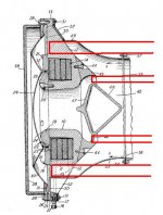
Your compression ratio estimates seem to be based on the diaphragm area divided by the area of the driver exit. But shouldn't they in fact be calculated as diaphragm area divided by the area of the aperture(s) at the point(s) of greatest constriction? The other calculation seems quite arbitrary and says nothing about the actual peak compression ratio of the system.
I have marked the apparent points of max constriction below.
Attachments
Last edited:
Hey Bill,
Think you must take the area of max constriction in the same plane.
By the way, aren´t there any more drawings of the thing?
Think you must take the area of max constriction in the same plane.
By the way, aren´t there any more drawings of the thing?
Last edited:
Hmm. Interesting thought, Lars. What is the rationale for the same-plane measurement vs. point of max constriction, especially as we're dealing here with two concentric apertures of differing geometry?
In terms of airflow, this does not make sense to me...
In terms of airflow, this does not make sense to me...
Last edited:
Tack out of the Wind
Model as two concentric but separate diaphragms [Sd1] & [Sd2] front cavities [Vc1] and [Vc2] and horn throats [St1] & [St2] and then combine them through another front cavity [Vc0]. Only the horn, voice coil and back chamber [Vb] and compliance [Vas] are are common elements here. Diaphragm and cavity modes are separate as well.
Regards,
WHG
Right Church, Wrong Pew
The area of the horn joint is not where [St] is measured.
[St] is the area of the annular slit at the perimeter of the diaphragm for the example shown. The rest of the phase plug implements the beginning of horn flare.
Regards,
WHG
Hello,
Let's do the compression ratio estimation for the WE555.
The ratio between the active diameter of the diaphragm and the active diameter of the troat of the attached horn is 2.84, thus the comrpession ratio is (2,84)² = 8.
See attached graph
Best regards from Paris, France
Jean-Michel Le Cléac'h
The area of the horn joint is not where [St] is measured.
[St] is the area of the annular slit at the perimeter of the diaphragm for the example shown. The rest of the phase plug implements the beginning of horn flare.
Regards,
WHG
- Status
- Not open for further replies.
- Home
- Loudspeakers
- Multi-Way
- DIY bass compression drivers