Premium Resitor Kit for F5
Hi,
I'm interested to buy the this resistor kit from TechDIY.
I'm wondering if there is someone out there who has expereince with it?
It consists of:
2 x R1,R2 10 Ohm, 15W - Caddock MP915
2 x R5,R8 50 Ohm, 15W - Caddock MP915
2 x R11,R12 0.5 Ohm, 30W - Caddock MP930
Why is R5 and R6 rated at 50W? In the original design it is R5-R8 at 100Ohm.
Thx,
Mallard
R5-8 were originally two 100Rx 3W in parallel to give 50R each side.Hi,
I'm interested to buy the this resistor kit from TechDIY.
I'm wondering if there is someone out there who has expereince with it?
It consists of:
2 x R1,R2 10 Ohm, 15W - Caddock MP915
2 x R5,R8 50 Ohm, 15W - Caddock MP915
2 x R11,R12 0.5 Ohm, 30W - Caddock MP930
Why is R5 and R6 rated at 50W? In the original design it is R5-R8 at 100Ohm.
Thx,
Mallard
TechDIY use one 50Rx 15W instead.
Don't forget to turn the bias pot to zero current before you switch the amp on for the first time 😉
By the way, the bias pot shouldn't be excessively sensitive, maybe you want to check your board?
Hannes
Thanks Hannes. I have those red board Chinese offerings. I did check resistor values when installing them. The multi turn pots are 5K but it is difficult to make small adjustments. I might have created a monster with the power supply? It is a 400va transformer with 18 volt secondaries. Positive and negative legs each have two 51,000 uf can caps with a 2 mH chock tieing them together on their voltge leg. I am seeing 27 volts DC with no load. One bridge rectifier.
those Caddock needs to be heatsinked to have that high dissipation, yes ?
Yes, except the 10R one's. They are rated 2W free air.
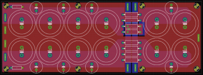
New CRC Supply. Based on Cvillers CRC supply, but with room for more caps.
The 3 small caps pr rail in the first C is to give a more total ripple current and secondly to lower the total ESR of the first C. The small cap in the second C is only there to lower the total ESR of the last C.
Big caps are 35 mm diameter, 10 mm pitch snap-ins, small caps are 16 mm diameter, 7,5 mm pitch leaded. Resistors are ment to be 5W resistors and lastly for connection to the PSU Fast on tabs are used.
A big board and unfortunately quite expensive to manufacture but what the hell, you only live once.
Ordering just 2 would cost around 25-30 Euro pr board. Once you get to 10 boards the price per board drops to 15 Euro or around that amount. Order 100 boards?, well, then they are almost laughably cheap.
The wonders of large scale manufacturing.
Attachments
Last edited:
Yes, except the 10R one's. They are rated 2W free air.
For those who're using these Caddocks, how did you manage the heatsink mounting? I'm using Cvillers V1.1 boards. It's seems to be quite difficult to get them tight on the heatsink, don't they?
Rgds,
Mallard
Big caps have lower esr than small ones. Same for ripple rating.The 3 small caps pr rail in the first C is to give a more total ripple current and secondly to lower the total ESR
Four big caps will more than suffice for ripple managing.
The first three small caps will do little there.
Why not three big ones on each side of the resistor.
Don' be afraid by ripple in first caps, it is the RMS value of established ripple that counts.
In PSUD, delay the simulation by one second and look at RMS value, it is not so high.
Also, the ripple capability of a cap is way higher when it is cold.
Ripple rating is RMS value at rated temperature.
Last edited:
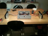
Well I fired my new F5 build up tonight and lo and behold, it actually worked with no hassle!!
I biased it up as far as 500mV - enough to prove it was working outside in the workshop. When I bring it into the house I'll need to trick about with the biasing a bit. Like myother build, this one has no protection/thermistors. But, I used 9240/240 in the other one, whereas I have fairchilds in this one. Also, I've bigger nicer transformers in this one. Both are dual mono in one chassis.
Photos to follow soon... this one is built on a alu head from a car engine. Big difference in temperature between the workshop and inside in the house (its final home) but at 500mV bias I could keep my fingers on the mosfet body - I'd estimate 50 degC. Given that its 20 deg warmer inside, it seems the head might... just might... work out as a heatsink for those of us working on the cheap.
Anyway, more testing to follow and more to discover about the heat dissipation from the head.
Fran
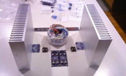
Photos to follow soon... this one is built on a alu head from a car engine.
Fran
have you kept the water cooling too 🙄
Hah!! no....
Seriously though..... if you had a look at an alu head from a relatively modern car - they are full of channels, with good air space inside, usually good flat spots suitable for mounting the mosfets and diodes. Easy to machine and tap too.
I'm told that the head holds about 80% of the coolant, so lots and lots of channels in there. I removed the valves, followers, plugs, studs, etc etc etc. power washed it with diesel to get most of the oil out, blew out the remainder with an airline. Used a wire brush on an angle grinder to clean up the rest, blew a few coats of primer, colour and lacquer and she was ready to go.
Its just as much work as assembling a chassis (more actually)... but it was free.
Fran
Well, I just think its poor form to announce you have a DeLorean powered F5 and not post photos.
Rover actually!!
Patience, patience..... it might blow a head gasket when I bring it inside and all this will be for nothing!
Patience, patience..... it might blow a head gasket when I bring it inside and all this will be for nothing!
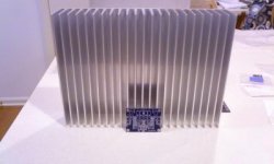
Nice!
Plenty of heatsinking you have here 😉
Looks like 7x10 pieces from heatsinkusa. I have the very same setup and they are just barely adequate. Hovers around 48-50 deg C most of the time.
Looks like 7x10 pieces from heatsinkusa. I have the very same setup and they are just barely adequate. Hovers around 48-50 deg C most of the time.
I guess they will all reach that temperature, sooner or later, given the bias
what might be different could be device case temperature
and room temperature might have less influence
may result in greater temperature stability
to improve, think convection inside the box
use it to increase airflow on the outside

- Home
- Amplifiers
- Pass Labs
- F5 power amplifier