contradictio in terminis
So, according to you, C1 < C2 is non-optimal, right?
 Maybe my sense of logic falls short, but I would think if there are non-optimal ratios, then there must also exist optimal ratios. Or do you mean all ratios are non-optimal anyhow? 🙄
Given the performance of TPC vs TMC, I would opt for the latter. 😀
With TPC C1 should be larger than C2, ..............
So, according to you, C1 < C2 is non-optimal, right?
There is no such thing as an optimum ratio. .......
Maybe my sense of logic falls short, but I would think if there are non-optimal ratios, then there must also exist optimal ratios. Or do you mean all ratios are non-optimal anyhow? 🙄Given the performance of TPC vs TMC, I would opt for the latter. 😀
Last edited:
obvious requirement
I suppose you meant it sarcastically, didn't you? 😉
Regarding the other requirement (C1>C2), I think it's 'utter nonsense' (his language, not mine). See, if not already done: http://www.diyaudio.com/forums/soli...lls-power-amplifier-book-118.html#post2412205 and this one: http://www.diyaudio.com/forums/soli...erview-negative-feedback-311.html#post2367976 Clearly, C1<C2 gives better results.
Cheers,
E.
I think everyone is agreed on that requirement.
I suppose you meant it sarcastically, didn't you? 😉
Regarding the other requirement (C1>C2), I think it's 'utter nonsense' (his language, not mine). See, if not already done: http://www.diyaudio.com/forums/soli...lls-power-amplifier-book-118.html#post2412205 and this one: http://www.diyaudio.com/forums/soli...erview-negative-feedback-311.html#post2367976 Clearly, C1<C2 gives better results.
Cheers,
E.
TMC transitions the Miller pick-off point from the output stage back to the VAS at high frequencies.
If this were true then it would mean the resistor connected to the output provides feedback transmission that falls with frequency. An imposibility.
Hi Bob,
Same minds, same thoughts. 😉 see: http://www.diyaudio.com/forums/soli...ogy-construction-troubles-32.html#post2412815.
What do you think about my latest sims, post 1169 and 1174?
Cheers,
E.
Hi Edmond,
I think your results are demonstrative that TMC is often better than TPC and that there seems no reason to use TPC when an amplifier with a good IPS/VAS is used.
For reference below, I have included a zip file that has two simulations of the amplifier I quoted results on earlier. Note that this file uses the models that I have posted on my website and which I believe to be better than most of those out there.
One simulation uses TMC and yields the results I quoted earlier (THD20 =0.0017%, 7th=3e-6). The other uses TPC that is set sufficiently agressive (by making R1 appropriately small) to achieve the same results for both THD-20 and 7th.
Note further that C2=5C1 for the TMC and C1=C2 for TPC. I have found that the use of identical C1, C2, R1 for TPC and TMC does indeed usually yield the same distortion results, but that TPC and TMC have different preferences for the ratio of C1 to C2. For example, if the TMC amplifier here is made into TPC by connecting R1 to ground, the same distortion performance is achieved but there is an anomoly in the closed loop frequency response that I cannot at this time explain.
Similarly, if you do TMC with C1=C2 with the same agressiveness in R1 to achieve 0.0017% distortion, there is also an anomoly in the closed loop frequency response.
So, TPC and TMC give about the same distortion result with identical components, but this is academic because each technique wants to have a different ratio for best performance. This is what I have been trying to say all along, perhaps not very well. It is thus silly to require the use of the same set of components for an honest apples-apples comparison. It is more appropriate to compare the techniques when each is set agressively enough to yield the same distortion performance, if possible.
Notably, the TPC amplifier with equally low distortion as the TMC amplifier exhibits 67% small-signal squarewave overshoot and +3dB closed loop gain peaking. Large signal squarewave response exhibits ringing.
Cheers,
Bob
Attachments
If this were true then it would mean the resistor connected to the output provides feedback transmission that falls with frequency. An imposibility.
no, it means that at high frequencies, the cap connected
to the vas output has lower impedance that the said resistor...
Isn t this obvious??????....
Notably, the TPC amplifier with equally low distortion as the TMC amplifier exhibits 67% small-signal squarewave overshoot and +3dB closed loop gain peaking. Large signal squarewave response exhibits ringing.
67% small-signal squarewave overshoot & ringing suggests your amp. is borderline stable. This implies component values for degeneration & compensation may well be incorrect. Check your loop gain. Also use phase lead comp.
Last edited:
It looks like the phase margin for the TPC version is a bit low in the loop around the output stage. It also has a lower crossover frequency at 1.2 MHz compared to 1.7 MHz for the TMC version.
The gain in the loop is the same at 60 kHz though at about 46 dB.
The gain in the loop is the same at 60 kHz though at about 46 dB.
Attachments
67% small-signal squarewave overshoot & ringing suggests your amp. is borderline stable. This implies component values for degeneration & compensation may well be incorrect. Check your loop gain. Also use phase lead comp.
Hi Mike,
This is just what it takes to obtain TPC performance equal to TMC performance - you know as well as anybody that TPC inevitably results in overshoot and frequency response peaking (assuming no phase lead crutch is used in the feedback path). The more agressive you make TPC to get lower distortion, the higher price you pay in transient behavior and stability. The large-signal ringing, though small, results from the fact that margins do decrease in the real world due to signal swing, especially when driving a 4 ohm load.
Mind you, this amplifier with TPC is not anything I would build or recommend; it is merely for comparison to show what you get when you try to get distortion performance from TPC that is as good as that easily obtainable from TMC.
The TMC version is rock stable, with no overshoot, no frequency response peak, and good phase and gain margins.
I urge you to choose different compensation values for this amplifier and simulate it to see if you can do better.
I also will be happy to see what you can do with this if you put in some lead compensation. Once again, however, I remind you that the TMC amplifier needs no lead compensation to perform really well.
Cheers,
Bob
John Atkinson informs, via the Sterophile blog, that the book is up for review early in 2011.
Here's something that gives similar loop gain for both TPC and TMC.
The input current to the VAS has already reached 10 degrees of lag coming from the input stage compared to the output so something is needed to make up for this. There is also a difference in that the TMC network gives built-in phase lead directly to the VAS which then needs to be added externally for the same loop gain shape.
While the TMC version may load the VAS less the TPC version draws less current from the input stage.
Attachments

Hi,
When one checks for phase lag, should he (a) value output against input of IPS or (b) feedback input of IPS against input of IPS?
In my case (a) seems fine with PM : 60° and GM : -12dB
but in case of (b) I cannot say because the phase starts to go positive (which is the same as -180 going to -360 right?) but in the meantime there is no amplification anymore (way below 0 -> -16dB) that is between both ips nodes (which is allways less than 0) on the other hand this positive phase (positive feedback) happens where the output vs input is still amplifying (near zero however).
i hope i explain myself right
thnx
olivier
John Atkinson informs, via the Sterophile blog, that the book is up for review early in 2011.
2011, let’s hope that Mr. Atkinson will have his focus on modern circuits, part 6 in Bob’s book. 🙄
Hi
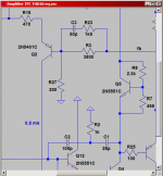
I have made an amp, using very different C values and ratios compared to Edmond and Bob’s ideal and “optimum” C’s, BTW the C connected to the VAS is the smallest one.
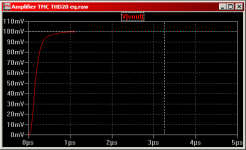
This is the THD20.
DC COMPONENT = 1.574083E-04
HARMONIC FREQUENCY FOURIER NORMALIZED PHASE NORMALIZED
NO (HZ) COMPONENT COMPONENT (DEG) PHASE (DEG)
1 2.000E+04 4.023E+01 1.000E+00 -9.073E+00 0.000E+00
2 4.000E+04 9.140E-05 2.272E-06 6.073E+00 2.422E+01
3 6.000E+04 3.910E-05 9.719E-07 1.765E+02 2.037E+02
4 8.000E+04 7.973E-06 1.982E-07 -8.831E+01 -5.202E+01
5 1.000E+05 3.117E-05 7.749E-07 -4.818E+01 -2.815E+00
6 1.200E+05 1.526E-05 3.793E-07 -5.481E+01 -3.685E-01
7 1.400E+05 1.523E-05 3.787E-07 1.039E+02 1.674E+02
8 1.600E+05 6.941E-06 1.726E-07 -1.797E+02 -1.072E+02
9 1.800E+05 9.698E-06 2.411E-07 9.025E+01 1.719E+02
10 2.000E+05 6.760E-06 1.680E-07 9.137E+01 1.821E+02
TOTAL HARMONIC DISTORTION = 2.673929E-04 PERCENT
I must be doing something that is very wrong, or?
I know nothing
I have made an amp, using very different C values and ratios compared to Edmond and Bob’s ideal and “optimum” C’s, BTW the C connected to the VAS is the smallest one.
This is the THD20.
DC COMPONENT = 1.574083E-04
HARMONIC FREQUENCY FOURIER NORMALIZED PHASE NORMALIZED
NO (HZ) COMPONENT COMPONENT (DEG) PHASE (DEG)
1 2.000E+04 4.023E+01 1.000E+00 -9.073E+00 0.000E+00
2 4.000E+04 9.140E-05 2.272E-06 6.073E+00 2.422E+01
3 6.000E+04 3.910E-05 9.719E-07 1.765E+02 2.037E+02
4 8.000E+04 7.973E-06 1.982E-07 -8.831E+01 -5.202E+01
5 1.000E+05 3.117E-05 7.749E-07 -4.818E+01 -2.815E+00
6 1.200E+05 1.526E-05 3.793E-07 -5.481E+01 -3.685E-01
7 1.400E+05 1.523E-05 3.787E-07 1.039E+02 1.674E+02
8 1.600E+05 6.941E-06 1.726E-07 -1.797E+02 -1.072E+02
9 1.800E+05 9.698E-06 2.411E-07 9.025E+01 1.719E+02
10 2.000E+05 6.760E-06 1.680E-07 9.137E+01 1.821E+02
TOTAL HARMONIC DISTORTION = 2.673929E-04 PERCENT
I must be doing something that is very wrong, or?
I know nothing
Bob, Thanks for the asc, but I'm confused - I just started poking at the sim and find the fft is the flat/rising spray of harmonics that usually indicates "hard" nonlinearity, some stage is limiting (or deadband?)
the diff pair bias looked light with extreme level of degen by other audio PA schematics I'm familiar with - so I bumped the tail current ~4x, cut degen R 10x - and anticipated fixing up compensation - but the amp still works in sim with 10x gain increase?? - some bouncing esp. with added Cload but not oscillating??
I suppose it could be called conservative design - but unless the models are just inadequate for stability estimates I would ask why such excess conservatism - leaving 20 dB distortion reduction on the cutting room floor so to speak
in any event it may not be not useful to explore compenstion in a sim that won't oscillate with 10x loop gain increase and 1nF direct Cload
I would like to know if this is the expected/intended behavior and maybe my instincts are just all wrong since I mostly look at Class Headphone level circuits with the luxury of >100MHz output devices
Last edited:
John Atkinson informs, via the Sterophile blog, that the book is up for review early in 2011.
Hi Jack,
I'm really looking forward to seeing that review!
Cheers,
Bob
jcx,
I just tried your change of values and it pushed up the gain crossover frequency to 7 MHz. The inductances in the output stage start getting significant up there and they are not modeled. I haven't tried but I suspect going for such a high crossover frequency in reality is a bit more troublesome than in the simulator... 😉
Bob,
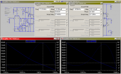
I played a bit with the TMC network and came to the same conclusion as syn08 did earlier but by a different method: the TMC network can, as far as the forward gain and feedback gain of the frontend is concerned, be replaced with a TPC network with the same component values plus an RC-network from the output of the amplifier to the base of the VAS. The capacitor value is the same as the TMC capacitor on the input side of the VAS (17 pF) and the resistor value is R * (1+Cout/Cin) (2.2 kohm * 6 = 13.2 kohm).
The loading on the VAS by the "equivalent" is different though, but can be lowered by changing the capacitors and resistor in the new TPC network to another combination which gives the same frequency of the high-frequency pole and HF asymptote but different impedance as seen from the VAS output.
I then took the current from the lead network into the virtual-ground VAS base and merged it with the current coming from the LTP into the wanted transfer function from the output voltage of the amplifier to the input current of the VAS. I then implemented it as a lead network across the feedback resistor instead, removing the RC network from the amplifier output to VAS base.
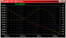
So in the end I ended up with 4879 ohms in series with 44 pF as a lead network which then goes across the 3800 ohm feedback resistor. In the TPC network I used 28 pF for both capacitors and 4 kohms for the resistor just like in your original TPC simulation. The simulation shows no overshoot for a 5 mV 100 ns risetime input step and the loop gain curve looks very much alike your original TMC implementation. The simulated distortion is 0.001723%.
The attached curves show loop gain for TPC + lead is in green and TMC is in red. The step response is for the TPC + lead version. The TPC version shows a little more phase lag which comes from the input stage.
I just tried your change of values and it pushed up the gain crossover frequency to 7 MHz. The inductances in the output stage start getting significant up there and they are not modeled. I haven't tried but I suspect going for such a high crossover frequency in reality is a bit more troublesome than in the simulator... 😉
Bob,
I played a bit with the TMC network and came to the same conclusion as syn08 did earlier but by a different method: the TMC network can, as far as the forward gain and feedback gain of the frontend is concerned, be replaced with a TPC network with the same component values plus an RC-network from the output of the amplifier to the base of the VAS. The capacitor value is the same as the TMC capacitor on the input side of the VAS (17 pF) and the resistor value is R * (1+Cout/Cin) (2.2 kohm * 6 = 13.2 kohm).
The loading on the VAS by the "equivalent" is different though, but can be lowered by changing the capacitors and resistor in the new TPC network to another combination which gives the same frequency of the high-frequency pole and HF asymptote but different impedance as seen from the VAS output.
I then took the current from the lead network into the virtual-ground VAS base and merged it with the current coming from the LTP into the wanted transfer function from the output voltage of the amplifier to the input current of the VAS. I then implemented it as a lead network across the feedback resistor instead, removing the RC network from the amplifier output to VAS base.
So in the end I ended up with 4879 ohms in series with 44 pF as a lead network which then goes across the 3800 ohm feedback resistor. In the TPC network I used 28 pF for both capacitors and 4 kohms for the resistor just like in your original TPC simulation. The simulation shows no overshoot for a 5 mV 100 ns risetime input step and the loop gain curve looks very much alike your original TMC implementation. The simulated distortion is 0.001723%.
The attached curves show loop gain for TPC + lead is in green and TMC is in red. The step response is for the TPC + lead version. The TPC version shows a little more phase lag which comes from the input stage.
Attachments
Last edited:
The loading on the VAS by the "equivalent" is different though, but can be lowered by changing the capacitors and resistor in the new TPC network to another combination which gives the same frequency of the high-frequency zero and HF asymptote but different impedance as seen from the VAS output.
Oops, I meant the high-frequency zero in the VAS transimpedance here, not pole.
- Home
- Amplifiers
- Solid State
- Bob Cordell's Power amplifier book