Utter nonsense.
Hi Mike,
I don't think multiple assertions of the same position without any foundation are helpful to people learning more about these two compensation techniques.
I hope that, rather than paticipants taking a win-lose position, we engage in enligtening debate that will expose the real engineering realities. Then everybody wins.
I gether from your last response to my earlier post that you agree that TPC cannot be made to do as well as TMC unless one uses a lead network in the feedback path. Do you agree with this?
Cheers,
Bob
Hi Bob,
I bought your book. Very enjoyable read. Thank you for publishing it and thank you too for the updates posted on your site.
Lastly, thank you for keeping this thread focused objectively on audio engineering. No thanks to those that try to sabotage it by posting emotional threads. Most of the topics that I am interested it are either covered in your book or in your many fact-filled postings here.
Merry Christmas!
Hi Mike,
I don't think multiple assertions of the same position without any foundation are helpful to people learning more about these two compensation techniques.
I hope that, rather than paticipants taking a win-lose position, we engage in enligtening debate that will expose the real engineering realities. Then everybody wins.
Cheers,
Bob
WORD!
Hi Bob,
I bought your book. Very enjoyable read. Thank you for publishing it and thank you too for the updates posted on your site.
Lastly, thank you for keeping this thread focused objectively on audio engineering. No thanks to those that try to sabotage it by posting emotional threads. Most of the topics that I am interested it are either covered in your book or in your many fact-filled postings here.
Merry Christmas!
Hi Arius,
Thanks very much for your kind words, and I'm really glad you're enjoying my book. The sprited exchanges we have on this thread help all of us learn more and refine our views. We are all members of this wonderful audio fraternity.
Merry Christmas!!
Bob
The compensation techniques of feedback systems are split in two classes: series compensation and feedback compensation.
Series compensation modifies the DC gain or dynamic of one or more elements in the main loop beeing a forward or a feedback element. Lead and Lag compensation are part of this class.
Feedback compensation is implemented by adding a feedback element which creates a two loop system. The inner loop is called the minor loop, the main one is called the major loop.
The objective of both compensation techniques is to maintain the ideal closed loop transfer function with acceptable dynamic performance.
The minor loop technique is very versatile and powerfull to modify the dynamic of a feedback system. Miller, Nested Miller, two pole compensation, TMC are minor loop techniques.
JPV
JPV
Hi JPV,
You've obviously been reading your Roberge! Good for you!
Hi Mike,
I don't think multiple assertions of the same position without any foundation are helpful to people learning more about these two compensation techniques.
Here is the foundation:
I have SHOWN that the TOTAL loop gain (that due to both the major loop and minor loop) enjoyed by the output stage with "TMC" and TPC is equal given the same component values. As SHOWN here:
http://www.diyaudio.com/forums/soli...terview-negative-feedback-55.html#post1160809
The later is true and correct as i hope you come to realise by the time you write the second edition of your book.
I have also SHOWN that this TOTAL loop gain is applied across the whole amplifier with TPC and just the output stage with "TMC". THAT is the foundation, and i am sorry, Bob, but "TMC" is just an electronic sleight of hand compared to TPC.
I gether from your last response to my earlier post that you agree that TPC cannot be made to do as well as TMC unless one uses a lead network in the feedback path. Do you agree with this?
Cheers,
Bob
Not so. I advocate lead (series) compensation because it increase phase margin. This is also true for other forms of minor loop compensation such as "TMC", but is of particular use in TPC because it negates the residual phase shift from the initial double pole roll off existing despite the cancellation provided by the amplifier's forward path zero.
Last edited:
"TMC" is just an electronic sleight of hand compared to TPC.
Just wondering if you've investigated VAS PSRR - TMP Vs TMC ?
Marry Christmas
Merry Christmas to all of my friends at DIYaudio. Your warm reception of my book has made this a very special year for me. I am truly blessed to have so many kind friends here.
Merry Christmas,
Bob
Merry Christmas to all of my friends at DIYaudio. Your warm reception of my book has made this a very special year for me. I am truly blessed to have so many kind friends here.
Merry Christmas,
Bob
Bob’s book only mention compensation and PSRR in passing – referring to possible improvement when both ends of the compensation are gnd referenced
He does show several “Miller Input” compensated (MIC) amp schematics
The best source for really understanding the issues is “A General Relationship Between Amplifier Parameters, And Its Application to PSRR Improvement” – a search should find the CiteSeerX page and you can grab the cached pdf for free
CiteSeerX — A General Relationship between Amplifier Parameters and its Application to PSRR Improvement
CMC, TMC, TPC are all limited by the (outer) loop gain being developed with respect to the power supply rail the VAS is referenced to – but in TPC that loop gain is much larger at audio frequencies so the PSRR is better than the 1st two
Sackinger’s paper shows several options in circuit diagrams and sims for those who make it past the physicist’s having fun part – and some of the mods can be applied to the “standard” power rail referenced compensation schemes
Last edited:
– but in TPC that loop gain is much larger at audio frequencies so the PSRR is better than the 1st two
Attachments
Merry Christmas to all of my friends at DIYaudio. Your warm reception of my book has made this a very special year for me. I am truly blessed to have so many kind friends here.
Merry Christmas,
Bob
Merry Christmas to you! And thanks for the very good book.
Hi Wahab, I actually do understand some of this stuff – and try to make that understanding accessible to others by supplying the reasoning, references and sims
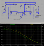
compensation components may be sometimes analyzed with "AC gnd" but you can miss critical properties if you don't use actual circuit connections - the "two-pole" resistor is properly referenced to the same supply rail as the VAS - sims and analysis that ignore power supply related properties like my 1st simplified circuit need intelligent modification to capture real circuit properties when you ask new questions
I modified my previous simplified compensation sim to explore PSRR
the g2,4 diff pair/mirror output and the g1,3 VAS spice models are referenced to the added -v_supply
to test PSRR the Vsource for the –v_supply has AC 1
as before the green trace is the “conventional Miller compensation” (left side “butterflied”/mirrored circuit with no compensation modifying resistors)
for the right side circuit when the variable "tmc" = 1 the compensation is actually "two-pole" with the resistor to the negative rail, clealy showing the superior negative PSRR in the yellow trace
red trace, V(out)@2 = TMC which as I stated based on the Sackinger paper's predictions is pretty much the same as "CMC"
positive supply rejection should be excellent for all of the sims - additional (mostly input) circuit detail would have to be added to capture CMRR properties
Attachments
Last edited:
Hi, Jcx
Thanks for the well argued explanations..
In matter of PSRR, we found ourseleves in the same
schemes as when computing OLG of the discussed compensations.
What count at first is the intrinsical OLG of the circuit before we
are to compensate it.
As already showed, TPC can have lower PSRR at high frequencies
since the VAS loading reduce this OLG at these frequencies.
But apart from this slight difference, PSRR will be comparable
since available NFB will act equally whatever the way it is used,
i.e fully used as GNFB or splitted in case of TMC/CMC...
Here is the foundation:
I have SHOWN that the TOTAL loop gain (that due to both the major loop and minor loop) enjoyed by the output stage with "TMC" and TPC is equal given the same component values. As SHOWN here:
http://www.diyaudio.com/forums/soli...terview-negative-feedback-55.html#post1160809
The later is true and correct as i hope you come to realise by the time you write the second edition of your book.
I have also SHOWN that this TOTAL loop gain is applied across the whole amplifier with TPC and just the output stage with "TMC". THAT is the foundation, and i am sorry, Bob, but "TMC" is just an electronic sleight of hand compared to TPC.
Not so. I advocate lead (series) compensation because it increase phase margin. This is also true for other forms of minor loop compensation such as "TMC", but is of particular use in TPC because it negates the residual phase shift from the initial double pole roll off existing despite the cancellation provided by the amplifier's forward path zero.
Hi Mike,
Here's the problem: I don't take your theoretical arguments as adequately convincing of your assertion. Theory is great, and it teaches us a lot, and often lends insight. But it is also often frought with errors and assumptions. The scientific method is to test the theory. In this case, that is simulation. You can say all you want about loop gain around this and that, and what component values you want to use, but I will not be convinced until you show that your theory is confirmed by simulation.
Once again, if you are claiming equality of loop gain around the output stage if identical components are used for TPC and TMC, then I assert that that is not convincing because you are applying an unreasonable constraint on the TPC and TMC approaches.
In spite of their topological similarity, TPC and TMC are different in their approach to achieving reduced distortion while maintaining stability. TMC transitions the Miller pick-off point from the output stage back to the VAS at high frequencies. TPC seeks to increase global loop gain by steepening the open-loop rolloff slope. These are two very different approaches. It should come as no surprize that the optimum values of compensation components may be different for each.
You are correct that lead compensation in the feedback path can improve phase margin, and that is true for most compensation schemes. But you should not have to depend on the use of lead compensation in TPC to make it as good as TMC without lead compensation.
My amplifier designs have plenty of phase margin without resort to lead compensation in the feedback network. I prefer to avoid the possibility that EMI will be fed back to the input stage from the speaker end of the system.
Cheers,
Bob
My position is near Mike’s as far as I can tell
I had hoped that the Blackman inspired output conductance sim I showed earlier would be convincing that the greater feedback of TPC and TMC are externally observable by comparing both to the same amp with CMC
http://www.diyaudio.com/forums/soli...lls-power-amplifier-book-110.html#post2406839
after all we wouldn’t give TMC a 2nd look if it wasn’t reducing distortion and I think we agree that is because of “added feedback around the output stage”
The argument on principle is that added feedback (externally observable as output impedance reduction/conductance increase) has an unavoidable cost in stability and that TMC by using about the same added feedback as TPC gives similar stability
I believe the controversy is over interpretation of the TMC “1st order” outer feedback loop gain measurement which appears to show nearly unchanged phase margin from normal “CMC”
I think you do have to look at the inner loop in this instance for the full picture- what happened to change your earlier view?
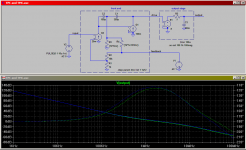
while my toy sim doesn’t have realistic enough output stage modeling – I believe your triple output should show added Cload destabilizing the TMC output much more than would be expected from the nominal 1st order appearance of the outer loop gain
and this is most easily viewed by looking at the gain "inside" the TMC resistor
the green trace is the output conductance of the “conventional Miller compensation” (left side “butterflied”/mirrored circuit with no compensation modifying resistors)
the two yellow are TPC,TMC output conductance
I had hoped that the Blackman inspired output conductance sim I showed earlier would be convincing that the greater feedback of TPC and TMC are externally observable by comparing both to the same amp with CMC
http://www.diyaudio.com/forums/soli...lls-power-amplifier-book-110.html#post2406839
after all we wouldn’t give TMC a 2nd look if it wasn’t reducing distortion and I think we agree that is because of “added feedback around the output stage”
The argument on principle is that added feedback (externally observable as output impedance reduction/conductance increase) has an unavoidable cost in stability and that TMC by using about the same added feedback as TPC gives similar stability
I believe the controversy is over interpretation of the TMC “1st order” outer feedback loop gain measurement which appears to show nearly unchanged phase margin from normal “CMC”
I think you do have to look at the inner loop in this instance for the full picture- what happened to change your earlier view?
...the global feedback gain crossover is only one parameter to keep an eye on. Those inner loops in any of the techniques can really get you, and must be watched closely...Bob
while my toy sim doesn’t have realistic enough output stage modeling – I believe your triple output should show added Cload destabilizing the TMC output much more than would be expected from the nominal 1st order appearance of the outer loop gain
and this is most easily viewed by looking at the gain "inside" the TMC resistor
the green trace is the output conductance of the “conventional Miller compensation” (left side “butterflied”/mirrored circuit with no compensation modifying resistors)
the two yellow are TPC,TMC output conductance
Attachments
Last edited:
Mine too it would seem.
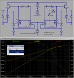
As the transfer function of the output stage and load, that is from VAS output voltage to final output voltage, is the biggest unknown in the loop what we should worry about as far as stability is concerned is the loop gain around the output stage. This is because its transfer function depends on large uncertainties like the relatively slow output transistors, significant parasitics, instantaneous output current, load impedance and so on. This loop gain is also what determines the amount of reduction of output stage distortion.
Whether the resistor in the compensation network goes to ground (TPC) or to the feedback node (TMC) is only of internal concern to the front end "black box" which has two inputs and one output. And this gain is, just as jcx and michaelkiwanuka point out, almost exactly the same for both cases. See attached figure. The plot shows loop gain for both the TPC (green) and TMC (blue) cases.
Attachments
Last edited:
Interesting analysis, I'd be interested in seeing the .asc file if you don't mind.
Another important issue is how they behave during clipping and overload with
at least a real output stage. My intuitive feeling is that TMC would be better
but I'd have to try the sims (Bob's that model an entire amp) or real hardware
to be sure.
Another important issue is how they behave during clipping and overload with
at least a real output stage. My intuitive feeling is that TMC would be better
but I'd have to try the sims (Bob's that model an entire amp) or real hardware
to be sure.
Last edited:
Once again, if you are claiming equality of loop gain around the output stage if identical components are used for TPC and TMC, then I assert that that is not convincing because you are applying an unreasonable constraint on the TPC and TMC approaches.
Identical component values is a perfectly reasonable constraint as it ensures equality of unity gain frequency between the two arrangements; precisely what is required for an apples and apples comparison.
My amplifier designs have plenty of phase margin without resort to lead compensation in the feedback network. I prefer to avoid the possibility that EMI will be fed back to the input stage from the speaker end of the system.
EMI feedback is a non-problem with a properly designed load isolation network.
- Home
- Amplifiers
- Solid State
- Bob Cordell's Power amplifier book