Hi,
to those that can look and see HF operation:
Can you explain why C2=220pF has been chosen at a high value?
Normally it's <<47pF.
Note that R23 is 100 ohms; the time constant of that branch is, mainly, a function of R23 and C2. If we were to scale the entire feedback network up so that R23 were 1K ohm then C2 would be 22pF, however the higher Z feedback network would be more sensitive to stray capacitance and Cin of the negative diff pair input. While we do sometimes mention actual component values here, what really matters is the transfer function of the network.
Here is the full article in case you are interested: http://www.swtpc.com/mholley/RadioElectronics/Dec1973/RE_Dec1973.htm
Last edited:
An early RCA transistor data book amp application schematic used output inclusive compensation cap, late 60s or early seventies
First I saw was: http://www.tcaas.btinternet.co.uk/jlhab2fig3a.gif
Wireless World, June/July 1970
/örjan
Wireless World, June/July 1970
/örjan
Last edited:
Hi Edmond, Bob
Many thanks for the references. I don't have the JAES paper to hand, but I have checked out the other two articles, and note that in both the Miller capacitor is simply connected to the output stage. I have certainly not had time to read all, or even a small part of the discussion on inclusive compensation in these columns, but I understand it is pretty much agreed that this form of it can never work in practice. Cherry claims in Part 2 of Ironing Out Distortion to have "published an analysis which has never been challenged."* but this is not the same as making it work for real. It is a matter of concern that neither of the Extreme Ironing articles contain a single measurement to back up the assertions therein.
I think I must have misinterpreted Bob's text, for I took "inclusive compensation" to mean "inclusive compensation that works". I think you are well-advised using the term "transitional Miller compensation" or TMC to avoid confusion, and I shall adopt the term and the acronym henceforth.
I can tell you that Peter Baxandall suggested to me the TMC method described in my Linear Audio article in a private document I received after his death in September 1995. I think it was written in 1994. I am aware of no public reference, but he sent me six pages of theoretical analysis, and he said he had "devoted much thought and experiment to the problem" which implies that he had personally tested it on a real amplifier. Whether he invented the technique is not clear, and that is what I would very much like to find out so credit can rest where it is due. It is a characteristic Baxandall idea- very simple but devastatingly effective. The HF THD improvement for the amplifier I have sitting on the desk at my elbow was rather more than three times- if the noise contribution was removed I think it would be more like 4 or 5 times
I have for many years resisted publishing The Baxandall Papers- some 50 pages of extraordinarily interesting material- as I was far some sure that that was Peter's intention. I think, however, that the risk they might be lost is too great and I will put the relevant six pages on TMC on my website at douglas-self.com as soon as I can, probably tomorrow.
Edmond, I have done a little searching and I note that you say I have "published an implementation of TMC that is far from optimal and poorly reflects the rationale behind the idea..." http://www.diyaudio.com/forums/solid-state/94676-bob-cordell-interview-negative-feedback-303.html
Very sorry to hear that. Perhaps you could point out my errors? I am always ready to be instructed.
* Feedback, sensitivity, and stability of Audio Power Amplifiers JAES May 82


First I saw was: http://www.tcaas.btinternet.co.uk/jlhab2fig3a.gif
Wireless World, June/July 1970
/örjan
In the postscript of Wireless World, december 1970, for his class A amp Linsley-Hood proposed about the same compensation, a 1000p cap from the VAS collector to the emitter of the input transistor, drawn dotted in horizontal position in fig. 1 of :
http://www.tcaas.btinternet.co.uk/jlh1970.pdf
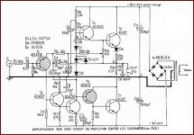
However, Bailey used an RC circuit in series (100 Ohm, 220 p) for the same kind of compensation in his 30-Watt amp, wich was detailed in Wireless World, May 1968, pp 94-98 (first attached picture)
It seems, this circuit was modified in november 1968 leaving out the 100 Ohm resistor (second attached picture).
For first two parts Bailey's article, send me an MP.
Last edited:
An early RCA transistor data book amp application schematic used output inclusive compensation cap, late 60s or early seventies
You probably mean this one. Can't date it exactly.
Attachments
You probably mean this one. Can't date it exactly.
That looks like some sort of translation, this is an early and similar RCA reference design but it does not use MIC:
Bob this is what I believe is the basis for the Citation 12 by the way:
http://www.diyaudio.com/forums/soli...-12-substitute-transistors-3.html#post2355300
That looks a bit like the "Brute 70" published in the Feb. 1967 issue of Popular Electronics:
http://www.swtpc.com/mholley/PopularElectronics/Feb1967/PE_Feb_1967_pg43.jpg
http://www.swtpc.com/mholley/PopularElectronics/Feb1967/PE_Feb1967.htm
Last edited:
Bob,
thank you for the information. We can agree that any other solution is better than the strongly detrimental additional base-to-collector capacitance, which is a brusque but efficient form of dominant-pole frequency compensation. However, it should be clear from any detached analysis that all methods are detrimental.
thank you for the information. We can agree that any other solution is better than the strongly detrimental additional base-to-collector capacitance, which is a brusque but efficient form of dominant-pole frequency compensation. However, it should be clear from any detached analysis that all methods are detrimental.
TMC
Hi Douglas,
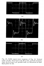
As far as I understand, tens maybe even hundreds of Cherry's designs has been built by his students. In the JAES paper he also showed some oscilloscope pictures (see blow). So we can safely assume that his amps do work in real life. But..... These are not just "output inclusive compensation" amps. If we look at his recommendations to make them work (see 3rd pic), he also put 30-50pF caps between the base and collector of the drivers. Effectively, this means an additional shunt compensation at the VAS output!. IOW, it's a hybrid form of compensation. Should we call it 'HMC'? 😉
If that's is the case, he must have said something about measuring results.
Also, I like to know what capacitor ratio (C1:C2) he was using (or recommending). Perhaps 1:1, just as you did?
It's also a very characteristic Edmond idea. 😀 And indeed, it's 'devastatingly effective'.
That's right, 4 to 5 times. However, you told me (about ten years ago) that the results were not 'exciting' (your words). Why? It still puzzles me.
That would be very appreciated.
I'm very sorry too.
The rationale behind the idea is a smooth transition between ordinary Miller compensation (at HF) and output inclusion compensation at AF, without (significantly) altering the gain and phase response of the global NFB loop (i.e. no 'kinks'). With a capacitor ratio of 1:1, this is not possible. If C1=C2=220pF, as shown in your own article, the effective Miller cap at HF is 110pF, while at AF it's 220pF, two times higher!* This means that at AF, 6dB of the potential loop gain is thrown away. As a result, 6dB more distortion and only half of the slew rate. IOW, if the potential improvement of TMC would be 12dB, then half of the baby is thrown out with the bathwater.
If the capacitor ratio is 1:5 or even 1:10, the 'wasted' gain is much smaller and the performance much better.
Cheers,
E.
* Funny enough, you also pointed this out in your article.
Hi Edmond, Bob
Many thanks for the references. I don't have the JAES paper to hand, but I have checked out the other two articles, and note that in both the Miller capacitor is simply connected to the output stage. I have certainly not had time to read all, or even a small part of the discussion on inclusive compensation in these columns, but I understand it is pretty much agreed that this form of it can never work in practice. Cherry claims in Part 2 of Ironing Out Distortion to have "published an analysis which has never been challenged."* but this is not the same as making it work for real. It is a matter of concern that neither of the Extreme Ironing articles contain a single measurement to back up the assertions therein.
Hi Douglas,
As far as I understand, tens maybe even hundreds of Cherry's designs has been built by his students. In the JAES paper he also showed some oscilloscope pictures (see blow). So we can safely assume that his amps do work in real life. But..... These are not just "output inclusive compensation" amps. If we look at his recommendations to make them work (see 3rd pic), he also put 30-50pF caps between the base and collector of the drivers. Effectively, this means an additional shunt compensation at the VAS output!. IOW, it's a hybrid form of compensation. Should we call it 'HMC'? 😉
I think I must have misinterpreted Bob's text, for I took "inclusive compensation" to mean "inclusive compensation that works". I think you are well-advised using the term "transitional Miller compensation" or TMC to avoid confusion, and I shall adopt the term and the acronym henceforth.
I can tell you that Peter Baxandall suggested to me the TMC method described in my Linear Audio article in a private document I received after his death in September 1995. I think it was written in 1994. I am aware of no public reference, but he sent me six pages of theoretical analysis, and he said he had "devoted much thought and experiment to the problem" which implies that he had personally tested it on a real amplifier.
If that's is the case, he must have said something about measuring results.
Also, I like to know what capacitor ratio (C1:C2) he was using (or recommending). Perhaps 1:1, just as you did?
Whether he invented the technique is not clear, and that is what I would very much like to find out so credit can rest where it is due. It is a characteristic Baxandall idea- very simple but devastatingly effective.
It's also a very characteristic Edmond idea. 😀 And indeed, it's 'devastatingly effective'.
The HF THD improvement for the amplifier I have sitting on the desk at my elbow was rather more than three times- if the noise contribution was removed I think it would be more like 4 or 5 times
That's right, 4 to 5 times. However, you told me (about ten years ago) that the results were not 'exciting' (your words). Why? It still puzzles me.
I have for many years resisted publishing The Baxandall Papers- some 50 pages of extraordinarily interesting material- as I was far some sure that that was Peter's intention. I think, however, that the risk they might be lost is too great and I will put the relevant six pages on TMC on my website at douglas-self.com as soon as I can, probably tomorrow.
That would be very appreciated.
Edmond, I have done a little searching and I note that you say I have "published an implementation of TMC that is far from optimal and poorly reflects the rationale behind the idea..." http://www.diyaudio.com/forums/solid-state/94676-bob-cordell-interview-negative-feedback-303.html
Very sorry to hear that.
I'm very sorry too.
Perhaps you could point out my errors? I am always ready to be instructed.
The rationale behind the idea is a smooth transition between ordinary Miller compensation (at HF) and output inclusion compensation at AF, without (significantly) altering the gain and phase response of the global NFB loop (i.e. no 'kinks'). With a capacitor ratio of 1:1, this is not possible. If C1=C2=220pF, as shown in your own article, the effective Miller cap at HF is 110pF, while at AF it's 220pF, two times higher!* This means that at AF, 6dB of the potential loop gain is thrown away. As a result, 6dB more distortion and only half of the slew rate. IOW, if the potential improvement of TMC would be 12dB, then half of the baby is thrown out with the bathwater.
If the capacitor ratio is 1:5 or even 1:10, the 'wasted' gain is much smaller and the performance much better.
Cheers,
E.
* Funny enough, you also pointed this out in your article.
Attachments


every bit helps
Hi Bob,
I got 10.2ppm. 😀
BTW, did you know you also can 'TMCed' the shunt compensation? Now THD20=8.9ppm 😉
(see C5 & R27)
Cheers,
E.
Hi Doug,
[snip]
Edmond convinced me about three years ago that TMC was competitive with Hawksford Error Correction (HEC) in providing very low distortion, yet at a much lower cost. About three years ago I simulated a version of my MOSFET power amplifier using TMC instead of HEC and got THD-20 below 0.001% out to 200 kHz analysis bandwidth. That design, shown below, combined TMC with MIC. The TMC inner loop was tapped from the predriver so as not to overly load the VAS. With the VAS output node unconnected to the Miller feedback, a simple R-C shunt was added to the VAS output node to retain compensation loop stability.
Cheers,
Bob
Hi Bob,
I got 10.2ppm. 😀
BTW, did you know you also can 'TMCed' the shunt compensation? Now THD20=8.9ppm 😉
(see C5 & R27)
Cheers,
E.
Attachments

Hi Bob,
I got 10.2ppm. 😀
BTW, did you know you also can 'TMCed' the shunt compensation? Now THD20=8.9ppm 😉
(see C5 & R27)
Cheers,
E.
Hi Edmond,
But did you get 10.2 ppm with a single-pair MOSFET output stage with idle bias of only 150 mA?
Cheers,
Bob
Hi Bob,
That's right. I simmed the same schematic. Results are pretty close, aren't they?
Cheers,
E.
That's right. I simmed the same schematic. Results are pretty close, aren't they?
Cheers,
E.
More a circuit two pole with problems and solutions:
http://www.diyaudio.com/forums/soli...or-vas-clamp-vas-current-limit-blameless.html
http://www.diyaudio.com/forums/soli...or-vas-clamp-vas-current-limit-blameless.html
The six pages of The Baxandall Papers relevant to Transitional Miller compensation are now available at:
The Baxandall Papers: Transitional Miller compensation
Peter Baxandall speaks to you from beyond the grave.
The Baxandall Papers: Transitional Miller compensation
Peter Baxandall speaks to you from beyond the grave.
Thank you very much, Douglas.
As he was talking about R=68 Ohms and a transition frequency of 1 to 2MHz, this implies that C2>>C1.
Cheers,
E.
As he was talking about R=68 Ohms and a transition frequency of 1 to 2MHz, this implies that C2>>C1.
Cheers,
E.
Many thanks, Doug
Pages 1 to 29 are probably Baxandall's series "Audio power amplifier design" published in Wireless World between january 1978 and february 1979. It ended with these words :
"(To be continued)".
Pages 1 to 29 are probably Baxandall's series "Audio power amplifier design" published in Wireless World between january 1978 and february 1979. It ended with these words :
"(To be continued)".
Many thanks, Doug
Pages 1 to 29 are probably Baxandall's series "Audio power amplifier design" published in Wireless World between january 1978 and february 1979. It ended with these words :
"(To be continued)".
No. They are basically a (not unfavourable) commentary on my "Distortion In Power Amplifiers" series of articles.
The six pages of The Baxandall Papers relevant to Transitional Miller compensation are now available at:
The Baxandall Papers: Transitional Miller compensation
Peter Baxandall speaks to you from beyond the grave.
According to your sayings, that s 6 pages out of 50.
Would it be possible that mr Baxandall s beyond the grave
message be integraly published ?.
Undoubtly, the whole audio community would be enriched
by this respected author s investigations..
BTW, for a respected designer who is subscribed elsewhere,
it seems that the output coil is not included in the TMC loop.
The LR circuit is part of the OS devices caracteristics.
Last edited:
I never said his amplifiers didn't work. I said that it was a matter for considerable concern that he gave no measurements to back up his mathematics. I cannot tell you how many ingenious amplifier schemes I have seen that calculated and simulated wonderfully but were quite unworkable in practice.Hi Douglas,
As far as I understand, tens maybe even hundreds of Cherry's designs has been built by his students. In the JAES paper he also showed some oscilloscope pictures (see blow). So we can safely assume that his amps do work in real life.
On the other hand, I have met several people who tried to build NDFL amplifiers but could not stop them oscillating. Hard words were said.
I wouldn't compare yourself with Peter Baxandall if I were you.It's also a very characteristic Edmond idea. 😀 And indeed, it's 'devastatingly effective'.
I assume you are referring to a half-baked Inclusive scheme that appeared in WW a long time ago, which used small-signal transistors because it wouldn't work with power ones. If so, then the results were indeed unexciting. But I fear I drift off-topic.That's right, 4 to 5 times. However, you told me (about ten years ago) that the results were not 'exciting' (your words). Why? It still puzzles me.
The rationale behind the idea is a smooth transition between ordinary Miller compensation (at HF) and output inclusion compensation at AF, without (significantly) altering the gain and phase response of the global NFB loop (i.e. no 'kinks'). With a capacitor ratio of 1:1, this is not possible. If C1=C2=220pF, as shown in your own article, the effective Miller cap at HF is 110pF, while at AF it's 220pF, two times higher!* This means that at AF, 6dB of the potential loop gain is thrown away. As a result, 6dB more distortion and only half of the slew rate. IOW, if the potential improvement of TMC would be 12dB, then half of the baby is thrown out with the bathwater.
If the capacitor ratio is 1:5 or even 1:10, the 'wasted' gain is much smaller and the performance much better.
My version of TMC in the Linear Audio article makes no claim to be fully optimised in every way. It was intended to show the measured benefits of the approach on a real amplifier while being stable and repeatable, and it was based on one of the The Signal Transfer Company Blameless amplifiers to make experimentation easier for people. I pointed out in the article that there is a loss of feedback factor with the values used, but the fact that the semi-local loop includes the output stage more than makes up for it. I think it is significant that what may be a non-optimal implementation still gives rather exciting results.
I am well aware that the concept could do with some more work, but I'm afraid I have a book deadline to think of at the moment.
Last edited:
- Home
- Amplifiers
- Solid State
- Bob Cordell's Power amplifier book