Not debugged yet, but the gate to source was not connected on the pcb. Will do that tonight, I'm confident it will be solved!
Luck was good! Negative rail worked like a charm. 66vout with the Vresistor at 12k, will reduce tomorrow. Scope was clean for both + and -. In fact, in normal state, the trace has little jitters in it, but when the shunt is turned on, it goes perfectly straight.
Thanks again for all your help. I'll put up a few more photos tomorrow and in a few weeks the entire rig.
Regards,
Ken
Thanks again for all your help. I'll put up a few more photos tomorrow and in a few weeks the entire rig.
Regards,
Ken
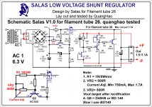
Salas shunt V1.0 with Filament Tube 26, tested by quanghao
Hi Salas, and all!
Salas V1.0 shunt used for Filament tube 26 is looking for a simple choice, I tried it and no buzzing noise, the tube 26 or the Rl load. AC voltage only 6.3V.
I have two changes:
1. R1 = 1R/5W
2.VR2 = 500R it is easily adjust the current
I claim no buzzing, noise, even when I use the input capacitor 12.000uF
You can watch and follow the wiring diagram below.
Thanks Salas !
Attachments
Last edited:
Is this the old design for member Disco in Holland? He had made one for #26 back then. Why you added adjustable current setting? To use with other DHT tubes too? Those tubes give different subjective impression with each filament powering technique beyond winning over hum issues, which is a big pain itself. What do you like more, voltage source (this one) or current source (Tentlabs, Rod)?
Luck was good! Negative rail worked like a charm. 66vout with the Vresistor at 12k, will reduce tomorrow. Scope was clean for both + and -. In fact, in normal state, the trace has little jitters in it, but when the shunt is turned on, it goes perfectly straight.
Thanks again for all your help. I'll put up a few more photos tomorrow and in a few weeks the entire rig.
Regards,
Ken
Great. The little jitters native to the scope when the regs are off are the probe's termination more likely. Nice to see more pics. Congrats. You can reduce Vo by two ways. One is trim the fix resistors, other is pick an adequately bit lower IDSS K170 than the one installed.
Is this the old design for member Disco in Holland? He had made one back then. Why you added adjustable current setting? To use with other DHT tubes too? Those tubes give different subjective impression with each filament powering technique beyond winning over hum issues, which is a big pain itself. What do you like more, voltage source (this one) or current source (Tentlabs, Rod)?
I put the VR2, for can get more mA, for some tube , EX;45, or 300B and not can change R1 for set current ( use Trimmer it is easy)
The sound is better Tentlabs, near the Rod!
But important, lower noise the Rod, I'm sure!
I like your design because:
1. it is simple
2. Can use many project, Ex, DAC, filament 26, Clock, Phono....
3. Make it cheap and easy!
Last edited:
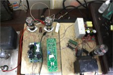
That is good feedback, thanks for the info. Let it burn for 48 hours and try different quality-speed bridge's diodes and big filter cap, to fine tune its tone.
That is good feedback, thanks for the info. Let it burn for 48 hours and try different quality-speed bridge's diodes and big filter cap, to fine tune its tone.
Please see some image!
Attachments
Don't know about PCB layout to help you, but I know that V1.2 is difficult to succeed on first shot for PCB. V1.2R has more noise due to bigger resistor in the base of the error amp and different shape/less bandwidth but no local compensation and easy to succeed for layout. Total noise is comparable due to less bandwidth though. Each one has a different subjective quality. V1.0RS, V1.2, V1.2R are all useful and mate differently to applications.
you said it will V1.2R easy to format my can try PCB?
So I want se your cricuit? Can you help me recommends??
V1 was very good for Filament Tube 26 at 1.1A wit 1.5V!
So I want se your cricuit? Can you help me recommends??
V1 was very good for Filament Tube 26 at 1.1A wit 1.5V!
All my reg circuits are here in the thread. The R versions are at post #3200. Klewis's 60Vo symmetric PCB build at #3339 is V1.2R for instance. For filament and heavy currents in general V1.0 is best.
All my reg circuits are here in the thread. The R versions are at post #3200. Klewis's 60Vo symmetric PCB build at #3339 is V1.2R for instance. For filament and heavy currents in general V1.0 is best.
Yes! i see V1 it is excellent for many many member Because:
1. it is simple
2.it is easy to make
3. Can use max 35V out and min 1.5V
4. Can use for Filament Tube 26, i have finis test it 2 days ago.
I want try to layout for V1.2R, ok i see it!
Thanks!
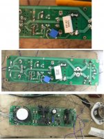
Hi,Try with remote sensing twisted pair wiring too.
I tried to persuade Q to move the sense traces to next to each other on the PCB, but he would not budge.
Now, when I see the untwisted wires, I finally understand why he can't understand why there could be further improvement.
Loop areas mean a lot when the equipment becomes a very sensitive receiver.
Hi,
I tried to persuade Q to move the sense traces to next to each other on the PCB, but he would not budge.
Now, when I see the untwisted wires, I finally understand why he can't understand why there could be further improvement.
Loop areas mean a lot when the equipment becomes a very sensitive receiver.
AndrewT Thanks your advance!
How twisted wires, as well as possible torsion, which is very effective way to reduce noise in any case of DIY.
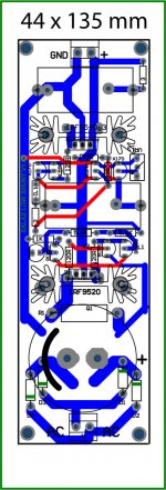
I do this PCB for multiple choice, so it has bigger size!
For example you can use the big A , as I've used for Filament 26 Tube
Last edited:
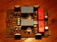
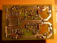
Updated photos of the board, top and bottom. The bottom image shows the current 12k resistors tacked on, easier to remove and replace until final vout is set. I've been messing with the layout and realized I can make the center part of the board symetrical about the horizontal (image horizontal) board centerline. So, I can either have the big blue caps close together at the center of the board or at the outboard edges. I'm thinking that at the center of the board will be better as it will keep the caps away from the heat sinks. Any votes?
Ken
Ken
Attachments

X2 with above, oh how I wish the V1 boards had bnc for sense, also the amphenol and hirose mini BNC would be perfect candidates.
also quanghao, I do like that you seem to be trying to make this one a bit smaller, but do not like that it seems to be at the expense of the ability to use to220 diodes 🙁
also quanghao, I do like that you seem to be trying to make this one a bit smaller, but do not like that it seems to be at the expense of the ability to use to220 diodes 🙁
- Status
- Not open for further replies.
- Home
- Amplifiers
- Power Supplies
- The simplistic Salas low voltage shunt regulator