[snip]
Seems to me that there is a 'net gain' of loop gain in the higher freq region.
jan didden
 What do you mean by 'seems to me'? Look at my graphs, please!!!!
TTPC
After fiddling a little with the compensation stuff, I managed to reduce the TDH20 even further: 2.5ppm.
This comes close to the performance of the ETMC variant.
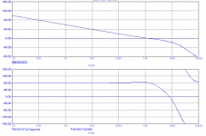
The (internal) Miller loop shows a healthy phase margin of 94 degrees at 12MHz.
After fiddling a little with the compensation stuff, I managed to reduce the TDH20 even further: 2.5ppm.
This comes close to the performance of the ETMC variant.
The (internal) Miller loop shows a healthy phase margin of 94 degrees at 12MHz.
After fiddling a little with the compensation stuff, I managed to reduce the TDH20 even further: 2.5ppm.
This comes close to the performance of the ETMC variant.
The (internal) Miller loop shows a healthy phase margin of 94 degrees at 12MHz.
Hello Edmond
Is this with and ideal current source for the VAS stage if so have you done sims with blameless current source or better.
Regards
Arthur
TTPC
Hi Arhur,
Indeed, simmed with ideal current sources. At the moment, I've no plans to investigate the TTPC topology any further, as I'm too busy with your phoenix amp 😉, in particular with the TT bias circuit. (so, one thing at the time).
Cheers,
E.
BTW, how about the Middlebrook stuff? Did you implement and try it already?
Hello Edmond
Is this with and ideal current source for the VAS stage if so have you done sims with blameless current source or better.
Regards
Arthur
Hi Arhur,
Indeed, simmed with ideal current sources. At the moment, I've no plans to investigate the TTPC topology any further, as I'm too busy with your phoenix amp 😉, in particular with the TT bias circuit. (so, one thing at the time).
Cheers,
E.
BTW, how about the Middlebrook stuff? Did you implement and try it already?
RFI
Hi Dimitri,
Out of curiosity, I tried that, but then the distortion at 20kHz increased by some 20dB
Cheers,
E
Hi Edmond, I'm afraid this will increase susceptibility to RFI substantially. Can you feed this network from other node, e.g. driver output?
Hi Dimitri,
Out of curiosity, I tried that, but then the distortion at 20kHz increased by some 20dB
Cheers,
E
Thank you Edmond for your efforts. I see that distortion is generated by output stage, as Cherry insisted.
dangerous take-off point
Hi Bob,
I agree with that. Nevertheless, it is possible to make such an arrangement rock stable. Below the magnitude and phase response of the local Miller loop. The circuit comprises a 'beta enhancement' tranny (resembling a Darlington) and a Hawksford cascode. The compensation feedback is taken from the pre-driver and the VAS output is loaded with a highly optimized R-C network.
Cheers,
E.
Hi Edmond,
[snip]
Taking the compensation feedback from the pre-driver can be especially dangerous when the VAS is a Darlinton-cascode, as the VAS self-loading is less and there are more transistors in the compensation loop, adding excess phase.
Cheers,
Bob
Hi Bob,
I agree with that. Nevertheless, it is possible to make such an arrangement rock stable. Below the magnitude and phase response of the local Miller loop. The circuit comprises a 'beta enhancement' tranny (resembling a Darlington) and a Hawksford cascode. The compensation feedback is taken from the pre-driver and the VAS output is loaded with a highly optimized R-C network.
Cheers,
E.
Attachments
TTPC
Hi Harry,
Now that I got far better results, I expected some response. Till now, nothing, nope, nada. 🙁
I suppose your silence has nothing to do with your membership 'over there'. 😉
Cheers,
E.
Edmond,
Have you ever tried TPC and TMC together*?
e.g. C1 = 1.2 nF, C2 = 68 pF, C3 = 1nF, R1 = 390R, R2 = 470R (see attached schematic)
What does your sim have to say about this?
*I guess strictly speaking this should be called TTPC (Transitional Two Pole Compensation)
Hi Harry,
Now that I got far better results, I expected some response. Till now, nothing, nope, nada. 🙁
I suppose your silence has nothing to do with your membership 'over there'. 😉
Cheers,
E.
Hi Harry,
Now that I got far better results, I expected some response. Till now, nothing, nope, nada. 🙁
I suppose your silence has nothing to do with your membership 'over there'. 😉
Cheers,
E.
Sorry! Been rather busy. But yes, very impressed with the results you've managed to get. Presumably you don't like it that much due to the resulting phase of the global loop? Would it be feasible to make an amp with ETTPC?
TTPC
Hi Harry,
Okay, never mind. Rather busy with the Middlebrook's gain probe, perhaps ? 😉
Well, I'm in dubio. On the one side, I don't like the phase dip and overshoot, on the other side, everything else is perfect, even the excellent properties of the local Miller loop (see post 3187). As a matter of fact, I feel a little frustrated, as we are almost there (an amp with an unbeatable performance/complexity ratio), except that tiny little detail.
Maybe. It's difficult to answer that question right now. I'll think about it.
Cheers,
E.
edit: Please, don't forget to rate this thread. 😀
Sorry! Been rather busy.
Hi Harry,
Okay, never mind. Rather busy with the Middlebrook's gain probe, perhaps ? 😉
But yes, very impressed with the results you've managed to get. Presumably you don't like it that much due to the resulting phase of the global loop?
Well, I'm in dubio. On the one side, I don't like the phase dip and overshoot, on the other side, everything else is perfect, even the excellent properties of the local Miller loop (see post 3187). As a matter of fact, I feel a little frustrated, as we are almost there (an amp with an unbeatable performance/complexity ratio), except that tiny little detail.
Would it be feasible to make an amp with ETTPC?
Maybe. It's difficult to answer that question right now. I'll think about it.
Cheers,
E.
edit: Please, don't forget to rate this thread. 😀
Last edited:
Input inclusive TMC (IITMC)
Hi Edmond,
Re TTPC - very impressive.
For some reason, I've been working on something I've named IITMC (input inclusive TMC), spice reckons around 5ppm THD (20kHz) - see attachment for schematic.
Spice indicates acceptable stability margins (approx 16dB and 70 degrees).
<1% overshoot observed with a square wave.
I would welcome any comments (from anyone).
Regards,
Ian
Attachments
IITMC
Hi Ihan,
I see a lot of nice features: TMC (of course 😉 ), a triplet output stage, a Wilson current mirror, a bootstrapped input impedance and a Hawksford cascode. Nothing wrong with that. 😀 However, I'm uncertain about the 'input inclusive' compensation. Are GM=16dB and PM=70 degrees simmed under best case conditions or under worts case conditions? In case of the latter, I would say just try (read: build) it. (If the amp oscillates, don't blame me, please!)
Cheers,
Edmond.
Hi Edmond,
Conditions: 8R load, 2V pk-pk squarewave (5ns risetime). I'll do some capacitive load tests.
Providing no-one has any serious reservations, I might commit this one to copper - but I'll include a layout feature so that it can use regular TMC if necessary.
By the way, since we last spoke (by email), I have built blameless TMC amps and using TMC, achieved a 15dB improvement in THD20 at 20k (measured with an AP analyser) - and observed no increase in overshoot or any signs of instability into a pure capacitive load. So, in case there are any remaining doubters, it definitely works. 🙂
Cheers,
Ian
IITMC in Bob's book
I've just been reading Bob's book, and noticed Fig 11.17 which uses IITMC fed from an output pre-driver! Looks like IITMC might work. Bob quotes simulation results. I wonder if he or anyone else has built it.
I've just been reading Bob's book, and noticed Fig 11.17 which uses IITMC fed from an output pre-driver! Looks like IITMC might work. Bob quotes simulation results. I wonder if he or anyone else has built it.
Hi Edmond,
Conditions: 8R load, 2V pk-pk squarewave (5ns risetime). I'll do some capacitive load tests.
Hi Ian,
So that's 87Vpp output voltage, right?
But what happens when the square wave is 0.5 below clipping?
Providing no-one has any serious reservations, I might commit this one to copper - but I'll include a layout feature so that it can use regular TMC if necessary.
If it's not stable, you also might tame the beast with an additional R-C networks, as C1 & R12 in Bob's fig. 11.17.
By the way, since we last spoke (by email), I have built blameless TMC amps and using TMC, achieved a 15dB improvement in THD20 at 20k (measured with an AP analyser) - and observed no increase in overshoot or any signs of instability into a pure capacitive load. So, in case there are any remaining doubters, it definitely works. 🙂
Cheers,
Ian
15dB is exactly the same figure as I got with simulation. 😀
Who says that distortion sims are pointless?

Cheers,
Edmond.
edit: You have a PM.
Last edited:
ETTPC
Hi Harry,
After some thoughts, it seems to me that combining ETMC with TPC will have little effect,
as the gain (at frequencies of interest) has already been maximized.
Cheers,
E.
Sorry! Been rather busy. But yes, very impressed with the results you've managed to get. Presumably you don't like it that much due to the resulting phase of the global loop? Would it be feasible to make an amp with ETTPC?
Hi Harry,
After some thoughts, it seems to me that combining ETMC with TPC will have little effect
,as the gain (at frequencies of interest) has already been maximized.
Cheers,
E.
For some reason, I've been working on something I've named IITMC (input inclusive TMC)
Regards,
Ian
What Douglas self calls input inclusive compensation is actually phase lead compensation taken from the output of the second stage.
compensation
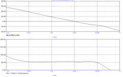
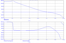
To all,
Below you see the phase and magnitude plots of the global FB loop of two nearly identical amplifiers, which differ only in the way of compensation. All other things are equal. Apart from THD, which of the two do you prefer (and why), A (1st pic) or B (2nd pic) ?
Cheers,
E.
To all,
Below you see the phase and magnitude plots of the global FB loop of two nearly identical amplifiers, which differ only in the way of compensation. All other things are equal. Apart from THD, which of the two do you prefer (and why), A (1st pic) or B (2nd pic) ?
Cheers,
E.
Attachments
Hi Ian,
So that's 87Vpp output voltage, right?
But what happens when the square wave is 0.5 below clipping?
If it's not stable, you also might tame the beast with an additional R-C networks, as C1 & R12 in Bob's fig. 11.17.
Cheers,
Edmond.
edit: You have a PM.
Hi Edmond,
Performance very close to clipping into just 100nF (no R) looks very good, approximately 10% -ve overshoot. I take on board your tips regarding C1 & R12 (many thanks) - if I build it, I'll definitely 'pad out' for them. PM answered.
Best regards,
Ian
- Home
- Amplifiers
- Solid State
- Bob Cordell Interview: Negative Feedback