No, just a simulation file with about parts that I had handy for IngemarR to see. Has higher voltage in that file for instance and 9540. The recommended values are after real scope DC flat line on phono B+ feed and subjective tests. I have it on power since then.
 Thank you!
P.S. The V1.2RposMedium as published can be used at 45 V for phono 60dB B+ but also up to 50 V for other design, I guess.
You just watch not to exceed the cascode elements Vmax, having at least 5mA to the Led, about 3mA to the shunt Mosfet driver BJT's resistor load, that kind of stuff when you scale. And above all comfortable dissipation for all the elements.
The Jfet in the Leds CCS will not take it. Replace with a ring of two BJTs or a suitable resistor.
The Jfet in the Leds CCS will not take it. Replace with a ring of two BJTs or a suitable resistor.
What is the most voltage to stick with the Jfet/CCS in the application (fixed tube neg grid bias.)
If you are talking the V1.0 that has a single Jfet local CCS for the 3 Leds, substitute a 10K 1W for that Leds Jfet, then it will take -50Vin -40Vout. With the Jfet, 35V out, 45V in max, still making it hot. Also put something on your PNP BCxxx error amp BJT, something to take some heat away, especially if to stay in a tubes amp box. For such an application you will not need more than 50-100mA current, and that to just keep the Mosfets happy. The grids won't draw. So you can up the setting resistor.
Thx for the schematic, Salas.
I hope it has not confused anyone
/IR
I hope it has not confused anyone
/IR
No, just a simulation file with about parts that I had handy for IngemarR to see. Has higher voltage in that file for instance and 9540. The recommended values are after real scope DC flat line on phono B+ feed and subjective tests. I have it on power since then.
If you are talking the V1.0 that has a single Jfet local CCS for the 3 Leds, substitute a 10K 1W for that Leds Jfet, then it will take -50Vin -40Vout. With the Jfet, 35V out, 45V in max, still making it hot. Also put something on your PNP BCxxx error amp BJT, something to take some heat away, especially if to stay in a tubes amp box. For such an application you will not need more than 50-100mA current, and that to just keep the Mosfets happy. The grids won't draw. So you can up the setting resistor.
And what about V1.2R for +50-60 V, 1 mA application?
Apart the crazy idea to waiste 50-100 mA for just 1 mA absorption (please don't tell to the polar bears...🙄)
Internally the reg it will need about 10mA for life support of its subsystems. Then to keep the Mosfets somehow at low rev idling, 50mA total I would consider as adequate. That would create 1.6W dissipation on the output Mosfet for -40V. Which is about where a KT-88 will be more or less biased in a push pull amp. Can be contained in a rudimentary sink. Use a BC556 with a TO-92 sink hat in the error amp for higher voltage.
Thx for the schematic, Salas.
I hope it has not confused anyone
/IR
No problem. Its nice to investigate all angles. If you ever make one on a perf board and will be working for you too in some application, let us know if you will figure out its real OLG contours. Its interesting.
If you are talking the V1.0 that has a single Jfet local CCS for the 3 Leds, substitute a 10K 1W for that Leds Jfet, then it will take -50Vin -40Vout. With the Jfet, 35V out, 45V in max, still making it hot. Also put something on your PNP BCxxx error amp BJT, something to take some heat away, especially if to stay in a tubes amp box. For such an application you will not need more than 50-100mA current, and that to just keep the Mosfets happy. The grids won't draw. So you can up the setting resistor.
how about using semisouth R550
 ? so the best way forward to getting +45vdc out with 200-300ma is biasing with resistor? could a string of 3-4 superbright white high VF LEDs work for high V ref? I dont mind ridculous solutions for stuff, but of course will just go the resistor and regular LEDs if its the best way forward.
this is with V1 for the D1 mosfet IV
see I could double this as backlighting for a front panel feature i'm planning, where I will mill out a 80mm diameter circle in the front panel and mount my rather special momentary push button in a slightly recessed 10mm thick piece of frosted clear acrylic as well as the lemo headphone connector and titanium volume knob. the white LEDs could illuminate this rather nicely at the same time as providing power indication and high quality referrence. is this insane?
 there are some nice ones from CREE at 10.7vf they will possibly need a heatsink of their own I guess
Last edited:
Talking about that Jfet. That one to replace with a resistor so to take the elevated input voltage and dissipation. I use a ring of two 65V Vceo BJTs there in V1.0 shunts for applications beyond 40-45Vin.
No don't use weird LEDs for Vref, they are possibly noisy.
No don't use weird LEDs for Vref, they are possibly noisy.
Attachments
OK got it, i'll just use a regular blue or white LED as part of one of my other circuits power on indication to provide back lighting then, was just trying to kill 2 birds with one stone (poor proverbial birds always cop it) BJTs it is, I prefer an active to passive CS
Salas,
Some months ago I was looking for a volume pot and you suggested trying the eBay (HongKong?) guy selling the DACT-type step attenuators, which are quite cheap. I bought a couple of them. They measured well and one of them has been working without problems, the other is not used yet. I think it sounds fine.
However, starting from a couple of days ago, sometimes I can hear some small "cracking" sound when turning the volume pot. So it is aging, like everything else.
This is intended as a report so that users can make informed decisions when buying the volume pots. I still think with their cheap prices they are worthy of what I paid for them, much better than those cheap ones one can get from Jaycar, etc. But to get a durable, ultimate one, I guess what you get is what you paid, or not? I have not tried the real one though, perhaps it won't last much longer? The price is robbery though.
Regards,
Bill
hey bill, are you sure there is no DC across the pot? not defending this guy if hes selling substandard goods (though I suppose if it was that cheap you dont know the origins) but its not unusual to get a crackling sound when you turn the pot if there is either DC present in the signal, or if one of the caps in the signal path is installed with reversed polarity
Salas,
Some months ago I was looking for a volume pot and you suggested trying the eBay (HongKong?) guy selling the DACT-type step attenuators, which are quite cheap. I bought a couple of them. They measured well and one of them has been working without problems, the other is not used yet. I think it sounds fine.
However, starting from a couple of days ago, sometimes I can hear some small "cracking" sound when turning the volume pot. So it is aging, like everything else.
This is intended as a report so that users can make informed decisions when buying the volume pots. I still think with their cheap prices they are worthy of what I paid for them, much better than those cheap ones one can get from Jaycar, etc. But to get a durable, ultimate one, I guess what you get is what you paid, or not? I have not tried the real one though, perhaps it won't last much longer? The price is robbery though.
Regards,
Bill
Hi Bill,
Cardas, DeoxIT, etc & have metal contact cleaner if you want to try, If I was you I do a test looking the contacts searching the bad green oxide or dust, if it's dust you can remove with a computer air spray, if it's green oxide is the worst case you must remove sanding the contacts with a lot of care.
Cheers
Felipe
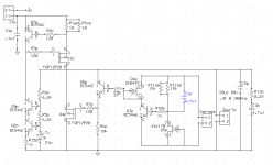
Salas,
I going to make boards for shunt 1.2R for 70Vin, 60Vout. Attached is my schematic of the positive voltage. R11ap and bp will be adjusted as required for the proper Vout. Just wanted to make sure I have this right.
Regards,
Ken
Fine. If every Q5 is not like the one you use for IDSS in your proto, each R11 combo will differ in practice so to match regs for Vo, correct. You could also use a bigger value C1p or double up, since you lowered R11s, for deeper filtering.
what is the tolerance on the 70V input?I going to make boards for shunt 1.2R for 70Vin, 60Vout.
if you build a 20V input and 10Voutput and apply a +-10% for mains variations then the effective input range is 18V to 22V with 10V output.
The devices can be cooled to suit the highest voltage input and the circuit can be tuned to operate correctly with the lowest supply voltage.
Apply a similar +-10% to your 70V input and you have an input range of 63V to 77V.
At 63V input there is insufficient Vdrop to allow the regulator to work.
At 77V input there is a lot of heat to dissipate.
Your design must take account of a range of working voltages and currents.
- Status
- Not open for further replies.
- Home
- Amplifiers
- Power Supplies
- The simplistic Salas low voltage shunt regulator