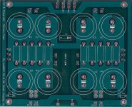
35 mm caps are too big for suds PSU PCB. Max. diameter is 30 mm.But it is possible Nelson used this one
Digi-Key - P6578-ND (Manufacturer - ECO-S1EA153EA)
Which has a diameter of 35mm
 & for fun!
Agree... or to take P. Daniel's or C. Viller's (universal) PSU PCB.Why not use the cap you want and wire it to the board with leads? I did this for my B1 when I went to Nichicon KG's because they were too big and had lugs instead of the snap in style termination.
& for fun!35 mm caps are too big for suds PSU PCB. Max. diameter is 30 mm.
In that case you will have no problem using the first recommendation
Digi-Key - P6577-ND (Manufacturer - ECO-S1EA153CA)
In that case you will have no problem using the first recommendation
Digi-Key - P6577-ND (Manufacturer - ECO-S1EA153CA)


Hey
Are you laughing at me or laughing at you😀
A little bit at me & a little bit at you (your humor) 😀
(BTW: I love Australia, since (old!) Seekers (Judith Durham etc. etc) )
Joke by side, thanks for your effort!
& for fun!To ma_coule: you have the same PCB´s what will be your solution?
I think to may be start a own thread for the power supply just for this amp, it seems a lot of peaple get trouble with this specific piece especialy with the 230V.
For now I think the best solution would be to get a ps pcb from Peter Daniel, as much as I regret it the PCB I have would realy need adjustments...
To ma_coule: you have the same PCB´s what will be your solution?
For now I think the best solution would be to get a ps pcb from Peter Daniel, as much as I regret it the PCB I have would realy need adjustments...
Following Jameshillj and you we have next possibilities: (Sudss, PDaniel's, CViller's, the last one is my "flying" PSU of SE amp Death of Zen - upon Rod Elliott's project)
Hm? 😕
Attachments
I have yesterday ordered the new ones from Peter Daniel.
Here is a list of components for them I put toggether from other threads:
Transfo 1 330VA - 2x18VAC SE-RKT 330 - 2x18 - 9.16A
Bridge Rectifier 2 35A - 200V TO-220/247 - Faston MB508
R1 to R8 4 0.47R - 3W 0.47 - MOX04 - 4W
R9 - R10 2 2.2K - 3W 2.2K - 3W
C1 to C8 8 15000*F - 25V 25V min
C9 1 .0033*F/250v Line Filtering - .0033*F/Line (.0022*F)
Fuse 1 1.25A - Slow Fuse
TH1 - Thermistor 1 5A - 10R - 25° Ametherm SL22 10005 - CL60 type
regarding the bridge rectifier, there will be an other solution comming with the PCB´s
see here:
http://www.diyaudio.com/forums/audio-sector/149672-universal-power-supply-pcb.html
I will definately leave Suds, PS PCB...
Here is a list of components for them I put toggether from other threads:
Transfo 1 330VA - 2x18VAC SE-RKT 330 - 2x18 - 9.16A
Bridge Rectifier 2 35A - 200V TO-220/247 - Faston MB508
R1 to R8 4 0.47R - 3W 0.47 - MOX04 - 4W
R9 - R10 2 2.2K - 3W 2.2K - 3W
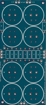
C1 to C8 8 15000*F - 25V 25V min
C9 1 .0033*F/250v Line Filtering - .0033*F/Line (.0022*F)
Fuse 1 1.25A - Slow Fuse
TH1 - Thermistor 1 5A - 10R - 25° Ametherm SL22 10005 - CL60 type
regarding the bridge rectifier, there will be an other solution comming with the PCB´s
see here:
http://www.diyaudio.com/forums/audio-sector/149672-universal-power-supply-pcb.html
I will definately leave Suds, PS PCB...
Hi Daniel,I have yesterday ordered the new ones from Peter Daniel.
Here is a list of components for them I put toggether from other threads:
Transfo 1 330VA - 2x18VAC SE-RKT 330 - 2x18 - 9.16A
C1 to C8 8 15000*F - 25V 25V min
If you go with P Daniels PSU PCB than, please, check C1 to C8 caps voltage.
You are now on higher voltage!
Transformer's data are a bit unclear (even to me). 😉
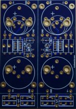
& for fun!Yes, only 4 caps but 50 volt ones.
Transformer is a 330VA, 2 x 18volt secondary & total seris current of 9.16 amps
Block Bridge -> discrete diodes, hopefully.
Transformer is a 330VA, 2 x 18volt secondary & total seris current of 9.16 amps
Block Bridge -> discrete diodes, hopefully.
Hi jameshillj,Transformer is a 330VA, 2 x 18volt secondary & total seris current of 9.16 amps
do you mean as mono supply to both channels (rails)?
& for fun!Yes, Single secondaries (36 volt) into seperate bridges, etc - better stereo image, IMO, despite this dual mono fettish - the amp draws about 2 x 80 VA, so enough power - a 500VA would be better - EI, or R-Core better still....
OK, now it's (very) clear! 😉Yes, Single secondaries (36 volt) into seperate bridges...
BTW, I'll go dual mono due to practical reason (two smaller 250W Tr, vertical -side by side- fixing). Will post sketch later.
& for fun!Serious effort going into your amp, ma - certainly should work really well!
If you want to really "Turbo charge" this amp, replace the 220uF electros C2, 3 and 4 with film caps.
I am currently using C2 = 33uF Auri - C3,4 = 44uF Russian K73-16 with MKP 1u5 Siemens B32654.
Each of the C5,6,7 have 22uF of the K73-16 across the 220uF Nichicon KZ.
R11, 18 are now high quality resistors (and R15 is next) - highly recommended.
jameshillj,Serious effort going into your amp, ma - certainly should work really well!
If you want to really "Turbo charge" this amp, replace the 220uF electros C2, 3 and 4 with film caps.
I am currently using C2 = 33uF Auri - C3,4 = 44uF Russian K73-16 with MKP 1u5 Siemens B32654.
Each of the C5,6,7 have 22uF of the K73-16 across the 220uF Nichicon KZ.
R11, 18 are now high quality resistors (and R15 is next) - highly recommended.
thank you very much for your friendly cooperation!
& for fun!Hello Guys,
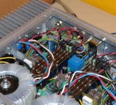
now the power supply besides, please look here:
http://hex.dan.sweb.cz/F3/DSC_0799.JPG
thats the B side of the amp, now since Im a noob I have no idea about it but why is there the, out+, in- and two gounds on one curent? at the right side of the pcb, current from the F3... is this right?
now the power supply besides, please look here:
http://hex.dan.sweb.cz/F3/DSC_0799.JPG
thats the B side of the amp, now since Im a noob I have no idea about it but why is there the, out+, in- and two gounds on one curent? at the right side of the pcb, current from the F3... is this right?
in - is ground, out+ is also ground, since it's an inverting amp out - is off cap, and goes to plus side of speakers. So you kind of hook your speaker terminals up backwards.
Hi @ll,
i've got a question about resistor values for the F3. Sadly most of the "voodoo"-Parts like Riken, AN-Tantals are only aviable in E12. it is possible to come close to a value if i parallel 2 resistors but the question is: It is necessary? There are especially two parts which I'm interested on: R1 and R2 which are in the signal path/NFB. R1 is 9,09K - so the usage of 9.1K would be a difference way below 1%. R2 is 47,5K - so 47K would be a difference of about 1%.
Would the usage be crucial?
All your Feedback is appreciated!
Galac
p.s. my english isn't that well but i hope it works ;-)
- Home
- Amplifiers
- Pass Labs
- F3 Builders Thread