Sounds like Z5 is backwards assuming that it is the zener in the CCS and you meant to say .68V not mV.
+1. if your z5=d3 on kristians PCBs.
It is hard to help with out the schematic you are using and where you are taking voltage measurements.
What are your source resistor drops.
Is the DC offset plus or minus.
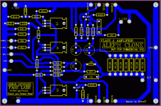
Who's PCBs are you using, have they been proven.
What are your source resistor drops.
Is the DC offset plus or minus.
Who's PCBs are you using, have they been proven.
Which end of the zener connects to the positive rail? Should be the cathode (band)
What is the resistance from the zener anode to ground or negative rail, depending on which you use?
What is the voltage between the CCS mosfet Source and the positive rail?
We're trying to be sure the CCS is working before we worry about the differential pair.
Measure the voltage referenced to ground at both ends of the zener, all three pins of the CCS IRF9610
Last edited:
1- Not sure about this, but measured across source resistor 0v. 2- Minus (6.40) Output + should be isolated from ground? 3- Brian GT.It is hard to help with out the schematic you are using and where you are taking voltage measurements.
What are your source resistor drops.
Is the DC offset plus or minus.
Who's PCBs are you using, have they been proven.

Yes, Cathode. The resistance was 0.00 . I was measuring from source point to +Vcc 0.9 going down and when reach 0.4-0.5 after more or less 5 mins started reading 283mv.Which end of the zener connects to the positive rail? Should be the cathode (band)
What is the resistance from the zener anode to ground or negative rail, depending on which you use?[wiki=]%[/wiki]
What is the voltage between the CCS mosfet Source and the positive rail?
We're trying to be sure the CCS is working before we worry about the differential pair.
Measure the voltage referenced to ground at both ends of the zener, all three pins of the CCS IRF9610
Last edited:
OK, I have no idea what you measured, but lets start here:
What is the voltage across R13? This should be rail-9.1.
What is the voltage across R14? Should be ~4V
What is the voltage to ground at Q1 and Q2 source pins? Should be ~4V
What is the voltage across R13? This should be rail-9.1.
What is the voltage across R14? Should be ~4V
What is the voltage to ground at Q1 and Q2 source pins? Should be ~4V
Well, I can tell you that your board is not a BrianGT board.
Bob, if you're using the manual can you email it to me. That's one I don't have.
Bob, if you're using the manual can you email it to me. That's one I don't have.
Bill, I'm just working off the board image and imagining the schematic.
Not Brian's latest board, but may be an early version.
Not Brian's latest board, but may be an early version.
[comment][/comment]5.6vOK, I have no idea what you measured, but lets start here:
What is the voltage across R13? This should be rail-9.1.
What is the voltage across R14? Should be ~4V[/QUOTE][comment][/comment] 0.00v
What is the voltage to ground at Q1 and Q2 source pins? Should be ~4V[/QUOTE][comment][/comment] Q1= 6.04v Q2= 6.04v
Last edited:
0.0 mv 😕The source voltages are high.
R11 still 0V?
how about the others I asked for?
Let's get them all in one post, please.
Also measure across R12.
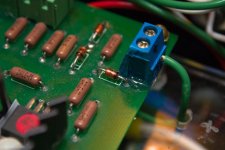
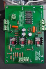
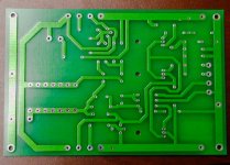
Post a picture of the bottom of your board. I suspect a solder bridge G-D on Q3
Also, please post rail voltages.
So, we need:
Rails
R11 = 0 Should be ~5
R12 should be 0
R13 should be rail -9.1
R14 should be ~4V
Also measure across R12.
Post a picture of the bottom of your board. I suspect a solder bridge G-D on Q3
Also, please post rail voltages.
So, we need:
Rails
R11 = 0 Should be ~5
R12 should be 0
R13 should be rail -9.1
R14 should be ~4V
Last edited:
Guess I should have specified a picture of your assembled board.
R13 - is that top to ground? Something is wrong there - the junction of R13 and Z5 should be 15V above ground. With power off, measure the value of R13.
Are the rails symmetric - +/- 24V?
So your CCS isn't working. Replace the zener with another. Then we'll have to look at Q3.
R13 - is that top to ground? Something is wrong there - the junction of R13 and Z5 should be 15V above ground. With power off, measure the value of R13.
Are the rails symmetric - +/- 24V?
So your CCS isn't working. Replace the zener with another. Then we'll have to look at Q3.
Last edited:
- Status
- Not open for further replies.
- Home
- Amplifiers
- Pass Labs
- My Dream Aleph 2 Coming True


