Why does it matter, you know that none of the readings make any sense whatsoever. He is obviously searching in the dark.
even if I'm completely satisfied with physical layout of your amp ( it's always nice to see detailed and carefully produced gadget ) , it's obviously time that someone skilled take care of finishing that amp ;
it's clear that you don't have basic knowledge in electronic , you can't learn that in few day's time , and messing with mains powered equipment is dangerous , when you don't have enough knowledge ;
even if you are careful with mains area of amp , it's easy to make mistake if you became frustrated wandering ... .
but relax - even Rome isn't built in one day .
Ok now I took some measures and still have the problem, recheck PS, voltages were fine, secondaries no load 37.7 vdc , then voltages from spkr - (output) to -v 52.5 vdc and to +v was -5.72, across R13= 5.12 vdc and across -v and +v = 45 vdc.
Your measurements show that your technique is off. If you have 37VDC (or were you measuring AC?) on the rails you cannot have 45V rail to rail and there is no way you can have 52V on the output.
A while back we suggested that you:
This is how Andrew suggested I do it.
Originally Posted by AndrewT View Post
FIRST.
no power.
Use a continuity tester or the lowest scale of ohms tester.
Find which tappings are on the same winding.
If any measure open circuit they are on a different winding. But check that the enamel insulation is not giving a false open circuit.
Label the windings, A, B, C etc.
SECOND.
insert the tappings of winding A into adjacent receptacles of an insulated terminal strip.
Insert the tappings of winding B into adjacent receptacles of an adjacent terminal strip.
THIRD.
power up using a bulb tester. Just in case you have mis-wired the primary.
FOURTH.
measure the voltage of the tappings on winding A.
do the same for each of the other windings.
Switch off or better, unplug from mains.
Do not measure the voltage between different windings. They are capacitively coupled and as soon as you load them the voltage changes due to the enormous impedance of the capacitive coupling. Ignore these misleading voltages.
FIFTH.
connect bridge rectifier AC terminals to winding A.
connect second bridge rectifier AC terminals to winding B.
SIXTH.
power up through the bulb tester.
measure the voltage across the AC terminals of the bridge rectifiers.
unplug.
SEVENTH.
connect smoothing capacitor across the + & - bridge rectifier terminals.
connect the other smoothing capacitor across the second bridge rectifier terminals.
EIGHT.
power up through the bulb tester.
measure the DC voltage across each smoothing capacitor.
Check the AC voltage across the AC terminals of the bridge rectifiers.
If the bulb stays off for all these tests then you have successfully wired up the PSU.
Hope this helps
cheers,
mymindinside
Thanks Mymindinside, I did follow the steps and could up the variac to full power, then measured across v+m and v- and got perfect 45 vdc, but then started to measure points like the service manual suggest : across r11=0 v , across z5=0.68 mv, dc offset is high 7.65 v and if I placed meter leds between speaker ouput + and ground getting 7.65 v also. Please help me to terminate this suffering. Thanks again.
You must not have followed the steps properly if your PSU is acting the way it is. Initially you had 7.65V output offset, now it is 52.5? Disconnect the amp from the PSU and go back to step one.
When you get to measuring DC voltages, measure with the black lead of your meter clipped to the common ground (that bus bar between the caps) - Do not move it. You might want to add a step 6a - connect your meter to the DC terminals of the bridges, power up with the bulb tester and verify that you have DC there. It will be lower than you would expect, but as long as it is ~2/3 of the AC voltage you are fine. Power down. go to step 7.
After step 8 you will need to bleed off the charge on the caps before connecting up your amp. Something like a 3k7 1W resistor across each rail will do. It will take a while to discharge. You can mount these before powering up on step 8, they will get too hot to touch. You can also make up a bleeder from several resistors of lower power rating. 3-4 ea. 10K 1/4W would do for temporary use.
Report back your readings: If you get something strange, STOP and report what you have done to that point and the readings.
AC voltage on each unloaded winding
AC voltage on each winding with a bridge connected
DC voltage across each bridge before connecting caps
Step 8 AC voltages across bridges
DC voltage ground to + rail
DC voltage ground to - rail
It would also help if you post pictures of the meter connection for each measurement, so that we are sure that you are measuring the proper voltage. This may require a bit of disassembly to get clear pictures.
Are the caps in the negative side of the filter bank connected properly (positive terminal to ground?)?
Once we are sure that your PSU is properly sorted, we'll take a look at the amp operation.
Last edited:
Another thought - When measuring the rail voltages in step 8, measure at the caps before and after the inductors.
Also, measure both rail voltages at 1 minute and 2 minutes after you shut down AC power.
Also, measure both rail voltages at 1 minute and 2 minutes after you shut down AC power.
I'll have to agree with what the guys said. Get someone trained/skilled to help you if you don't feel comfortable working with mains voltage. Then rework the PSU, check transformer, caps and the resulting voltages, then proceed to the audio circuit.
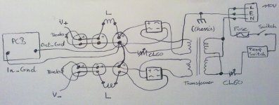
Attached you'll find what I intended to post earlier.
Attached you'll find what I intended to post earlier.
Attachments
Hi Bill, again thanks to take the time for this, later I'll remove the CL60 and will implement all changes that you and rodeodave suggest. Ok now I took some measures and still have the problem, recheck PS, voltages were fine, secondaries no load 37.7 vdc , then voltages from spkr - (output) to -v 52.5 vdc and to +v was -5.72, across R13= 5.12 vdc and across -v and +v = 45 vdc.
are you sure you wired the bridges right?
you got +52.5V spk- to V-. there you want -50V.
you get -5.72V spk- to V+. there you want +50V.
chek that you did not wire bridge V- to caps V+ or the other way, on one of the bridges.
Last edited:
Don't worry about this, that was when I started taken measurements and the secondaries were mix up, already fixed.did you measure at the trafo sec? and got 75Vdc?
you must measure Vac at this point.
Last edited:
Right Pair is 38.2 vacDave just accidentally drew two channels instead of one, ignore it.
Your PS is totally screwed up. You should have around +50 DC from the neg spkr term to the pos rail, -50 to the neg rail, and 100 volts from pos rail to neg rail.
Disconnect all 4 secondary leads from the bridges and measure the AC voltage of each pair. If they are not very close to the same there is no logical reason to go any further, your trafo is bad. They should measure around 35 volts AC or whatever the trafo label says.
Only if they are the same should you proceed any further.
Disconnect all the DC connections from the bridges and reconnect the bridges to the secondary trafo leads. Measure the DC voltage at each bridge output from plus to minus. If they are not very close to the same, one of the bridges is bad or the trafo is bad.
If things still check out correctly at this point then either you have seriously miswired the filter section or one or more of your caps is bad. Disconnect the amp board from the power supply until you have a properly working power supply. There is absolutely no reason to go any further until you do.
Attachments
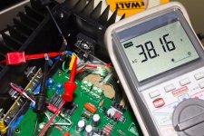
Left Pair 38.2 vac nothing connected. Are they close enough? Can I do next step?

 Trans secondaries are rated 37 vac.
Trans secondaries are rated 37 vac.

OK.
Which two of the four wires that connect to the plus and minus terminals are connected to the neutral (ground) of the filter section?
Which two of the four wires that connect to the plus and minus terminals are connected to the neutral (ground) of the filter section?
While you're at it, trace all four wires to their filter connections and label them with what they go to. We don't know if the colors of them mean anything so we are going to ignore the colors of the wires.
Yes I do, this is what I have, but going to changed it to + and - of each pairs.its okei. so your problem is in the caps or inductor coil.
do you use bleeders?

Last edited:
Black to neutral , Red to positive.OK.
Which two of the four wires that connect to the plus and minus terminals are connected to the neutral (ground) of the filter section?
Ahh - one wire from each bridge connects to the GROUND bus bar. Which ones? (hint - you gave the wrong answer above.)
Connect the one wire from each bridge to the bus bar, clip the black lead of your meter to the ground bar and measure the DC voltage to the unconnected bridge terminals. You should get a + and - voltage again.
Notice in your psu plan that one bank of caps connects the negative terminal to the ground bus and the other connects the positive terminal to ground. Verify the you have them connected that way.
Last edited:
- Status
- Not open for further replies.
- Home
- Amplifiers
- Pass Labs
- My Dream Aleph 2 Coming True