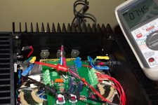
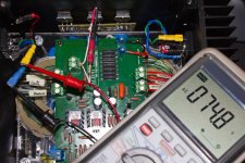
They should be very close to identical, and a few volts higher than the rated voltage on the tag.
Thanks Bill, I understand what you say, I got 42.1 vac no bridge and 41vdc with bridge and 28.3 vac and 27 vdc at the other side. That difference means the transf. is bad ? .Thanks for your help.They should be very close to identical, and a few volts higher than the rated voltage on the tag.
One weird thing or maybe not , with the side that measured 41 vdc with secondaries and a bank of caps connected to bridge took a measure to the other secondaries no caps no bridge, sec, directly to the meter is getting 75 vdc.why the rise in dc voltage, if I don't have the transformer connected to the bridge, when before I was getting 28 vdc .Something wrong here?
Last edited:
I don't understand what you are trying to do. The simple fact is your transformer is bad, unless your meter is faulty.
Draw what you are trying to do if you can.
Draw what you are trying to do if you can.
it seems that you know what you're measuring ;
but - we'll know too , if you draw simple schematic of xformer and exact voltage
according to your words - something is wrong , but only with schematic we can confirm is it or isn't
but - we'll know too , if you draw simple schematic of xformer and exact voltage
according to your words - something is wrong , but only with schematic we can confirm is it or isn't
it seems that you know what you're measuring ;
but - we'll know too , if you draw simple schematic of xformer and exact voltage.
Thanks Zen Mod, I'm 100% sure that you know how to measure, that's why I'm asking , please excuse my little to nothing knowledge about this and again thanks in advance. Here is what Am using.By the way, I wire primaries black-black together and red-red together.
Last edited:
if you are able to reach 37Vac on at least one secondary - primary connection is correct
so - trouble is if you don't have two identical voltages in two secondaries ; xformer is bad .
so - trouble is if you don't have two identical voltages in two secondaries ; xformer is bad .
if you are able to reach 37Vac on at least one secondary - primary connection is correct
so - trouble is if you don't have two identical voltages in two secondaries ; xformer is bad .
No, I'm not getting to identical voltages on secondaries, then this is a set back in the schedule of finish the Aleph 2. Zen Mod, your help was so great for me , the same for the other guys, I'll be back soon.
Unrelated to your transformer issue, but I think you ought to wire the mains earth directly to the chassis and use the CL60 from your star ground to the chassis. Hopefully that's the way you have it, but it is drawn with different grounds.
Unrelated to your transformer issue, but I think you ought to wire the mains earth directly to the chassis and use the CL60 from your star ground to the chassis. Hopefully that's the way you have it, but it is drawn with different grounds.
I have CL60 connected directly to ground at inlet power like you see in diagram, notice the ground connection from caps. Also have more ground connection seen in other diagram. Please can you explain cons to have the connection that I'm using and clarify a little bit about star grounding. Thanks Bob for your time.View attachment 20010112182421928.pdf
View attachment Aleph 2 Mainboard.pdf
With any resistance between the chassis and mains earth you can get voltage on the case above earth potential - possibly a shock hazard. I know, if any serious voltage develops the CL60 will conduct and lower its resistance, but the idea of a safety ground is to connect with the lowest possible resistance to earth. It probably doesn't matter much in real life, but why not go as safely as possible when it amounts to a minor change?
You get the same audio ground isolation effect if you move the CL60 to the connection between the copper bus bar and the chassis ground and connect the mains earth directly to the chassis.
You get the same audio ground isolation effect if you move the CL60 to the connection between the copper bus bar and the chassis ground and connect the mains earth directly to the chassis.
Hi JPDuarte,
i had a similar problem on my First Watt F2 build recently. the transformer had 2x18v secondaries, and the wires were mis-labelled. it turned out that i had connected my secondaries wrong, yet was getting a voltage reading that seemed right (18vac) i connected the wire pairs (what i thought was one winding) to a rectifier and crc filter and got a reading of 24vdc. if a load was applied to just one "secondary" then the voltage would sag from a nominal 24vdc to 6vdc and the voltage on the other wire pair would rise from 24vdc to 36vdc.
you can read about the problem here
see post 126
EDIT: just re-read the OP's posts. if the voltage on the secondaries is not the same without any load connected then it is probably a bad transformer.
hope this helps,
cheers,
mymindinside
Last edited:
You were right!!🙂 right now the amp is connected to my variac but don't know where to start taking measurements to know when to start upping the voltage.Hi JPDuarte,
i had a similar problem on my First Watt F2 build recently. the transformer had 2x18v secondaries, and the wires were mis-labelled. it turned out that i had connected my secondaries wrong, yet was getting a voltage reading that seemed right (18vac) i connected the wire pairs (what i thought was one winding) to a rectifier and crc filter and got a reading of 24vdc. if a load was applied to just one "secondary" then the voltage would sag from a nominal 24vdc to 6vdc and the voltage on the other wire pair would rise from 24vdc to 36vdc.
you can read about the problem here
see post 126
EDIT: just re-read the OP's posts. if the voltage on the secondaries is not the same without any load connected then it is probably a bad transformer.
hope this helps,
cheers,
mymindinside
This is how Andrew suggested I do it.
Hope this helps
cheers,
mymindinside
FIRST.
no power.
Use a continuity tester or the lowest scale of ohms tester.
Find which tappings are on the same winding.
If any measure open circuit they are on a different winding. But check that the enamel insulation is not giving a false open circuit.
Label the windings, A, B, C etc.
SECOND.
insert the tappings of winding A into adjacent receptacles of an insulated terminal strip.
Insert the tappings of winding B into adjacent receptacles of an adjacent terminal strip.
THIRD.
power up using a bulb tester. Just in case you have mis-wired the primary.
FOURTH.
measure the voltage of the tappings on winding A.
do the same for each of the other windings.
Switch off or better, unplug from mains.
Do not measure the voltage between different windings. They are capacitively coupled and as soon as you load them the voltage changes due to the enormous impedance of the capacitive coupling. Ignore these misleading voltages.
FIFTH.
connect bridge rectifier AC terminals to winding A.
connect second bridge rectifier AC terminals to winding B.
SIXTH.
power up through the bulb tester.
measure the voltage across the AC terminals of the bridge rectifiers.
unplug.
SEVENTH.
connect smoothing capacitor across the + & - bridge rectifier terminals.
connect the other smoothing capacitor across the second bridge rectifier terminals.
EIGHT.
power up through the bulb tester.
measure the DC voltage across each smoothing capacitor.
Check the AC voltage across the AC terminals of the bridge rectifiers.
If the bulb stays off for all these tests then you have successfully wired up the PSU.
Hope this helps
cheers,
mymindinside
Thanks Mymindinside, I did follow the steps and could up the variac to full power, then measured across v+m and v- and got perfect 45 vdc, but then started to measure points like the service manual suggest : across r11=0 v , across z5=0.68 mv, dc offset is high 7.65 v and if I placed meter leds between speaker ouput + and ground getting 7.65 v also. Please help me to terminate this suffering. Thanks again.
- Status
- Not open for further replies.
- Home
- Amplifiers
- Pass Labs
- My Dream Aleph 2 Coming True

